This paper was first presented at GPD 2023.
Link to the full GPD 2023 conference book: https://www.gpd.fi/GPD2023_proceedings_book/

Authors:
- Valérie Hayeza - Dow Silicones Belgium
- Jon Kimberlainb - Dow Silicones Corporation, USA
- Jie Feng - Dow Silicones Corporation, USA
Abstract
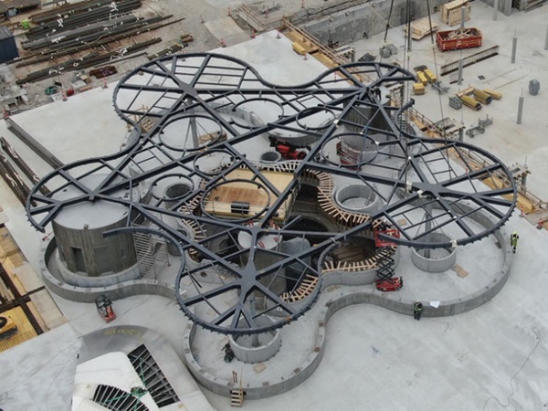
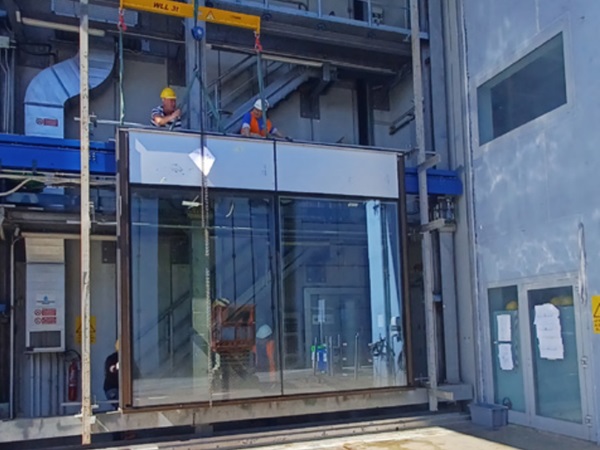
Modern free form glass architecture has become increasingly popular in the structural sealant glazing application, as demonstrated by many iconic building projects, such as Allianz tower in Milan. Among different technologies to manufacture such glass, cold bending is one of the most cost efficient and aesthetically pleasing solutions. In this process, flat glass panels are elastically deformed to follow the façade contours by bonding to a metal frame with a silicone sealant. This operation imposes a permanent bending force onto the silicone as the bent glass strives to return to its initial flat shape. This can lead to silicone creep and tear failure if the joint is not properly dimensioned.
Previous research by the authors has evidenced through a combination of experimental testing and finite element analysis how principal strain in the sealant needs to be limited to ensure durability and avoid tearing. This current research proposes an optimized methodology for cold bent glass and SSG design through a simulation-based DOE study for different glass and metal frame form factors as well as silicone sealant parameters. In addition to the level of cold bend glass deflection, metal frame and sealant thickness have the most significant effect on the peak strain in the sealant in the cold bent glass operation.
1. Introduction
Cold-bent glass units in façades have gained in popularity as architecture in commercial buildings is showing a trend to innovative, non-rectangular “organic” shapes. Structural silicone glazing (SSG) has been used successfully as retention method of the bending membrane. The cold bending operation will impose a permanent bending force onto the silicone sealant as the bent glass strives to return to its initial flat shape. This can lead to silicone sealant creep and tear failure if the SSG joint design is not properly dimensioned.
Different evaluation methods for joint dimensioning exist, using simplified analytical or semi-numerical calculation methods for the early design stage, to using Finite Element Analysis (FEA) for the final concept. Although FEA should result in more accurate estimates than more simplistic analytical techniques, caveats include longer computation times, need for appropriate material behaviour models for structural sealants and enough accuracy in the model. Even FEA will not be able to model all details of a design and needs to make some simplifications, so the results must be carefully discussed and validated. The goal of the current paper is therefore to propose an optimized methodology for cantilever cold bent glass and SSG design, combining the accuracy of FEA with the simplicity of an analytical equation. A simulation-based Design of Experiment (DOE) study for different glass and metal frame form factors as well as silicone sealant parameters was performed.
2. Experimental approach
2.1. Building the FEA model
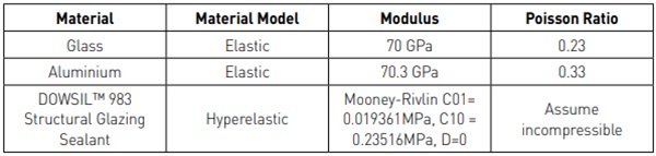
The numerical simulations were performed using a commercial Finite Element Analysis software ABAQUS. The silicone DOWSIL™ 983 Structural Glazing Sealant was assumed to be incompressible and fully integrated Hybrid hexahedral elements (C3D8H) were used to prevent element locking, i.e. exhibiting an unphysically stiff response to deformation. When relevant, glass, aluminum and structural sealant were modeled in the simulation based on their typical material behaviour, as summarized in Table 1. For the bi-component structural sealant, the design stress in tension is 0.14MPa, in dynamic shear 0.11MPa and in static shear 0.011MPa. The structural sealant hyperelastic material model was fully characterized through uniaxial tension, biaxial tension and planar tension testing (Dow 2023).
2.2. DOE model
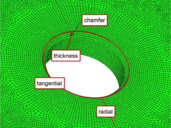
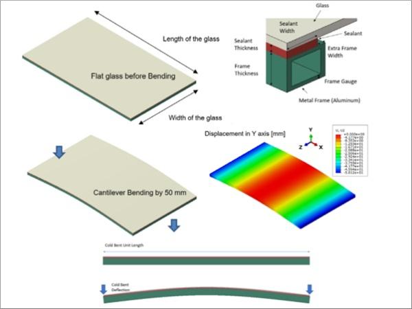
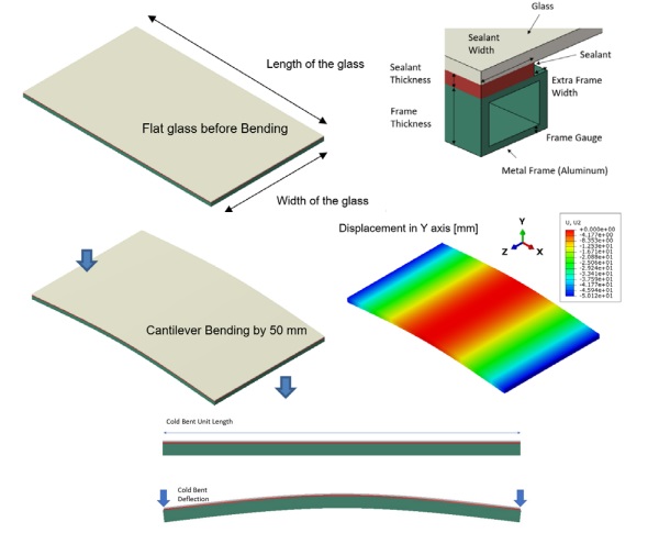
A cold bent glass unit usually consists of a glass panel, a metal frame (mostly aluminum) and a silicone bonding layer, as shown in Figure 1. The glass panel is first bonded onto the metal frame by the silicone sealant. Then, the whole unit is bent in one direction to form the curved glass unit in a cantilever beam layout, which will induce strain in the sealant. For this study, in the baseline design, a 914.4mm x 1524mm x 6mm glass was bonded on a 25mm x 25mm Aluminum frame using a 6mm x 20mm silicone joint.
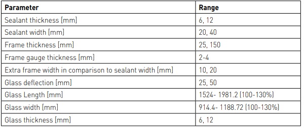
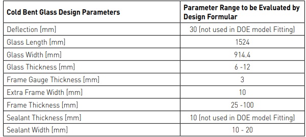
These parameters were consequently varied in a simulation based DOE through Full Factorial Design, as listed in Table 2. The selected range for each parameter is assumed to be representative of a majority of cold bending projects, based on the authors’ expertise. The sealant thickness of 6mm is the minimum required per SSG standards such as ASTM C1401 (ASTM 2014), ETAG002 (EOTA 2012) and a higher thickness of 12mm is normally required in case of cold bending to accommodate the higher deformation, but rarely exceeds this value. The sealant width is typically larger than in conventional (flat) SSG (evaluated range is between 20mm and 40mm), to compensate for the high loading during cold bending. The frame thickness ranges between 25 and 150mm. Similarly, the glass deflection in the cantilever is limited to 25mm and 50mm, as the authors have rarely encountered successful projects with higher values of bending.
The focus is on the evaluation of the SSG. Therefore, in terms of glass build up, a single glass layer is evaluated instead of a multi pane insulating glass unit. It is assumed that the IGU can be transformed into an equivalent thickness using ASTM E1300 (ASTM 2016) or similar standards. The glass length is set between 1524 and 1981mm whereas the glass width is varied between 914.4mm and 1188.72mm. These values are relatively small compared to the industry average but as will be seen in the results, results in a relationship which can be extrapolated to larger values. In this study, peak maximum principal strain was calculated at each integration point for the SSG sealant and output as the response for the DOE study. With the 2-level Full Factorial design, this DOE study intends to determine the critical design materials to guide the SSG sealant joint design for the cold bent glass.
3. Results
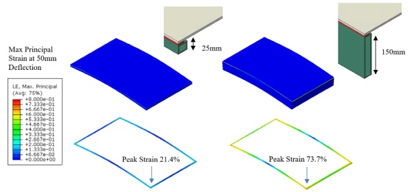
From numerical modeling for the cold bent glass bonded by SSG sealant, it is found that peak maximum principal strain in the SSG sealant can be significantly affected by several key design parameters. As shown in Figure 2, with same glass geometry (914.4mm x 1524mm x 6mm), SSG sealant design (20mm x 6 mm) and glass deflection (50mm), the peak strain in the SSG sealant can increase by 3X as Frame thickness increases from 25mm to 150mm.
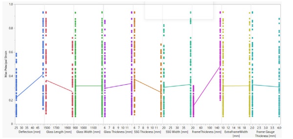
The effect of the cold bent glass design is further explored by modeling all possible design parameter combinations in Table 2 under two levels of cold bent deflection (25mm and 50mm). The peak maximum principal strain is calculated for the SSG sealant, as plotted in Figure 3.

It is found that within the range of cold bent glass design parameters in Table 2, increasing frame thickness and glass thickness will lead to higher strain in the sealant. By contrast, glass length and SSG thickness increase can significantly reduce the strain in the SSG sealant. It is expected that glass length increase will make the whole SSG system more flexible, and this will reduce the loading on the SSG sealant. As sealant thickness increases, it will have more capability to accommodate cold bent loading from the glass with reduced strain development.
The effect of the different cold bent glass design parameters is further ranked by a Pareto Plot, as shown in Figure 4. The Pareto plot exhibits the absolute values of the standardized effects from the largest effect to the smallest effect based on the calculated t ratio (significance level of a given parameter estimate). The effect of glass width is very small for cantilever bending, while frame thickness and SSG thickness have the most significant effect in this DOE study.
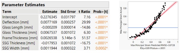
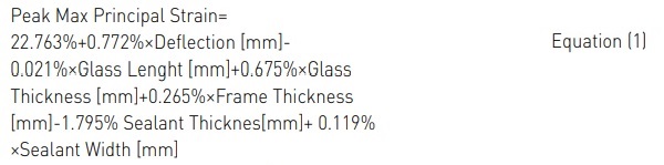
This study allowed determining an optimized design formula for glass, frame and silicone sealant joint for cold bent glass application. As the Glass width, Extra frame width and Frame gauge thickness have very small effect in this DOE design, they are not considered in the design formula for the cold bent glass, as shown in Figure 5 and Equation (1). Without considering higher order effect from the interaction of the design parameters, the R2 for the fitted equation is 0.89, which is close to 1, suggesting the fitted design formula is reasonably accurate for the design parameters evaluated in the DOE study.
![Fig. 5 SSG Cold Bent Durability Prediction by Combining Lab Scale test with Application Case [Kimberlain 2019].](/sites/default/files/inline-images/Fig5a_0.jpg)
With the fitted peak strain prediction formula for cold bent glass using Equation (1) and SSG sealant durability prediction equation based on peak strain (see Equation (2) and Figure 5), it is possible to perform a quick and earlystage assessment for a SSG sealant joint design for a cold bent glass without performing sophisticated numerical modeling by FEA simulation.

The effectiveness of this simplified early-stage design assessment for a SSG sealant joint design used in a cold bent glass is shown in Figure 6, Tables 3 and 4. For a selected cold bent glass design, different design parameters, such as Frame thickness and SSG sealant (see Table 3), can be quickly evaluated by the Design formula in Equation (1) and the calculated peak strain is very close to the strain predicted by FEA modeling, as shown in Table 4.
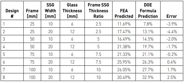
Moreover, it is observed that Frame / SSG sealant thickness ratio has a significant effect on the Peak maximum principal strain in the SSG sealant. Overall the SSG sealant durability is expected to increase with a reduced Frame / SSG sealant thickness ratio, as shown in Figure 6.
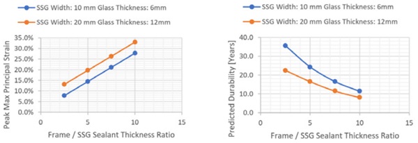
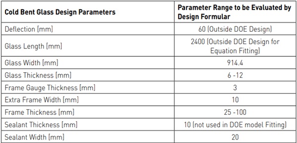
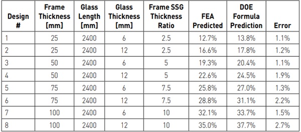
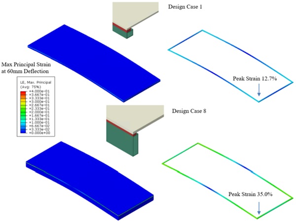
A few cold bent glass designs with 2400mm glass length and 60 mm glass deflection, both parameters being outside the DOE study range, are also evaluated for their suitability using the Fitted Design Formula, as shown in Table 5. Even when the glass size and cold bent deflection exceed the range of the DOE study, the predicted peak strain by the design formula (Equation 1) remains close to the peak strain predicted by the FEA based numerical modeling, as shown in Table 6 and Figure 7. This confirms the usefulness of the Design formula for early-stage SSG joint design evaluation before performing extensive numerical modeling.
4. Conclusion/Design Guidelines
The approach presented in this paper for joint dimensioning in cantilever cold bent units, is intended as a compromise, combining the accuracy of a full FEA to the speed of resolution of an analytical equation. Limitations exist due to the range selected for each parameter. Furthermore, the method assumes multi pane glazed units can be reduced to an equivalent single pane thickness, this transformation also remains an approximation. However, this approach is a first step towards using complicated FEA to derive simplified design methods which are better than analytical as they incorporate additional complexity such as frame geometry, glass thickness. This type of approach, combining FEA and DOE to obtain design guidelines, could be used for other types of applications, such as corner cold bending.
Further research is needed to understand the impact of test variability relative to a statistical relevance for failure prediction modeling which should include sample replicates and impact of ageing as well as further decreased percentages of loading. It is important to note that the provided laws are only applicable to the evaluated sealant. Further investigations are needed to ensure these laws can or not be extrapolated for other sealant types.
To conclude, as with any unique design, it is best practice to build a performance mock-up to validate the output of any FEA to ensure that there are no unintended interactions that would be detrimental to the durability of a design. All elements can impact the behaviour of the other elements such as glass thickness, sealant bite or frame rigidity. A mockup, for instance of part of a façade or at least for one façade element will allow to study deformations under real conditions and can be also used to prove safety and durability under accelerated ageing or long term weathering.
5. Disclaimers
THIS INFORMATION IS OFFERED IN GOOD FAITH FOR YOUR CONSIDERATION, BUT WITHOUT GUARANTEE OR WARRANTY (EXPRESS OR IMPLIED), AS ANALYTICAL CONDITIONS AND METHODS OF USE OF THE INFORMATION AND MATERIALS DESCRIBED HEREIN MAY VARY AND ARE OUT OF DOW'S CONTROL. ALTHOUGH THIS INFORMATION IS BASED ON DATA DOW BELIEVES TO BE RELIABLE AND ACCURATE, WE DO NOT INTEND FOR YOU TO USE, AND YOU THEREFORE SHOULD NOT CONSTRUE, THE CONTENTS OF THIS DOCUMENT AS BUSINESS, TECHNICAL OR ANY OTHER FORM OF ADVICE. WE RECOMMEND YOU DETERMINE THE SUITABILITY OF THE INFORMATION AND MATERIALS DESCRIBED HEREIN BEFORE ADOPTING OR USING THEM ON A COMMERCIAL SCALE. DOW ASSUMES NO LIABILITY IN CONNECTION WITH THE USE OF THIS INFORMATION
® ™ Trademark of The Dow Chemical Company ("Dow") or an affiliated company of Dow
6. References
ASTM C1401, Standard Guide for Structural Sealant Glazing (2014)
ASTM E1300, Standard Practice for Determining Load Resistance of Glass in Buildings (2016)
Dow, DOWSIL™ 983 Structural Glazing Sealant Simulation Data Sheet, www.dow.com, accessed 21st April 2023
EOTA, ETAG 002, Guideline for European technical Approval for Structural Sealant Glazing Kits (2012)