This paper was first presented at GPD 2023.
Link to the full GPD 2023 conference book: https://www.gpd.fi/GPD2023_proceedings_book/

Authors:
- Valérie Hayez - Dow Silicones, Belgium
- Jon Kimberlain - Dow Silicones, USA
- Jie Feng - Dow Silicones, USA
Bonding of glass onto aluminum frames, known as Structural Silicone Glazing (SSG), has been applied for more than 50 years on facades. Traditionally the silicone bite is calculated using a simplified equation described in guidelines such as ETAG002 or ASTM C1401, which assumes a homogenous stress distribution along the sealant bite. Although this approach will remain a valid method for which there is proven performance, recent research has indicated that joint dimensioning can be optimized for excessively large joint bites such as projects that are being designed to perform in high velocity wind zones. As joint bite dimensions increase, the distribution of stress in the structural silicone sealant diverges from homogeneity in mostly tension under negative wind load.
The divergence is due to the rigidity of the sealant as a function of glass rotation where mixed modes of stresses can be observed in compression, tension and shear along the width of the bond. Alternative methods of compliance to the conventional design methods are important as it allows a greater design freedom without sacrificing long term durability. Physical prototypes from small scale H-pieces to full scale panels measuring 914mm by 1524mm were tested with different joint aspect ratios varying between 2:1 to 4:1 width to depth ratios. Finite element analysis of the tested units provided insight into the behaviour of sealant distribution and potential failure identification. Based on the performed testing, new methods of compliances for dimensions joints are proposed beyond normal conventional methods outlined in ETAG002 and ASTM C1401.
1. Introduction
When silicone structural glazing (SSG) design guidelines were developed more than 20 years ago, design strength of the sealant was largely based on meeting a minimum safety factor for tensile strength. As sealant technology has evolved, some would consider this design strength to be low as tensile properties have increased. But the initial standards were purposeful to compensate on the unknowns in building performance and delivery of a project. Factors such as material ageing, production tolerances, or unknown component interactions were believed to be muted by this de minimus design strength determination.
This would allow compensating for not only these factors but difference in how stress distributes in actual joints versus the joint design when using the simplified joint dimensioning calculation method referred to in standards like ASTM C1401 (ASTM 2019) or guidelines for structural glazing like ETAG002 (EOTA 2012). This calculation method only considers the joint to be in mostly tension under negative wind-load, whilst the rotation of the bite due to the deflection of the glass pane is neglected. Additional factors influencing the joint behavior such as its geometry and the Young modulus, are not considered.
Today, architectural designs tend towards increased glass pane dimensions and extreme windloads for which conventional calculation methods combined to a high safety factor (or a low design stress) result in economically and aesthetically unacceptable large bites.
Alternative improved calculation methods can be used for the joint dimensioning, such as Finite Element Analysis (FEA) or advanced analytical equations (Descamps 2017, Descamps 2018) which are able to predict similar results as FEA. As the calculation method accuracy increases, questions arise about how much the design (allowable) stress could be increased and several more or less complex methods have been suggested (Drass 2020a, Drass2020b, Maniatis 2016). Another question to answer, which is more interesting to the industry from a practical point of view, is whether the design strength can increase safely while using proven simplified design methods in current standards. To answer this question, it is important to understand for which design parameters it is appropriate to apply a higher design strength without losing design safety or durability due to potential fatigue effects.
The current paper compares experimental results obtained at different scales (from TAjoints to large scale 914mm by 1524mm) with the predictions of the analytical equations and FEA. Guidelines are provided to the conditions in which a higher design strength can be used for the joint dimensioning.
2. Experimental approach
2.1. Sample description
Different structural sealant sample designs were evaluated in the study to understand the sealant failure criteria, as shown in Table 1.
The Sample Design 1 and 2 are essentially the TA joint design based on ETAG002 standard (EOTA 2012). Several dimensions were investigated. The first is the conventional design with aspect ratio = 1, whereby a 12mm x 12mm x 50mm structural sealant is applied between two 6.35 mm x 24 mm x 75 mm Aluminum plates. The other TA joints have increased aspect ratios, obtained by applying 16mm x 8mm x 50 mm (AR = 2), 24mm x 8mm x 50mm (AR = 3) and 32mm x 8mm x 50mm (AR = 4) structural sealant between the aluminum plates.
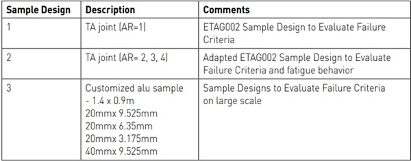
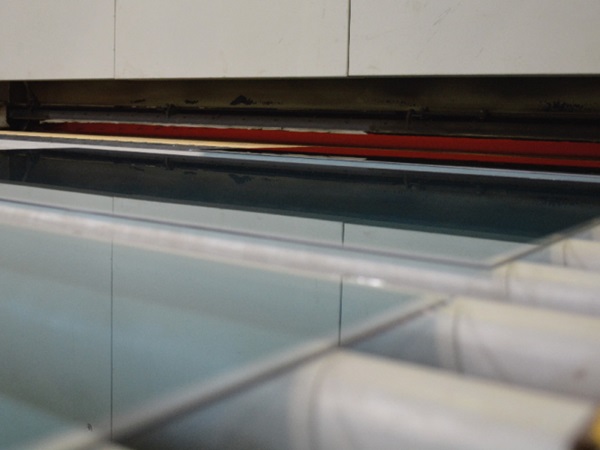
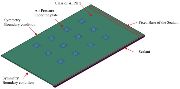
Sample design 3 is a customized sample aiming to validate on a large scale the observations made on H-pieces (figure 1 and 2). A 6.35 mm thick aluminum plate, having the same flexural rigidity as glass is bonded on 4-sided on an aluminum frame using DOWSIL™ 983 Structural Glazing Sealant.
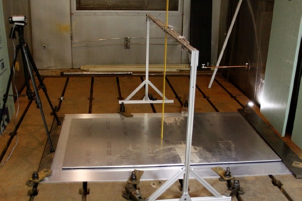
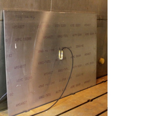
One 914.4mm x 1524mm aluminum plate was bonded to an aluminum frame of dimensions 1219.2mm x 1828.8mm x 6.35mm. Different joint dimensions were used for the bonding using two sided tapes to define the joint geometry. Three samples had a bite of 20mm and a varying thickness to obtain aspect ratio of respectively 2.1 (thickness= 9.525mm), aspect ratio 3.2 (thickness = 6.35mm) and aspect ratio of 6.3 (thickness = 3.175mm). The last sample had a doubled bite of 40mm and thickness of 9.525mm, resulting in an aspect ratio of 4.2. The bottom plate was held in place with standoffs attached to limit deflection during air pressurization of the cavity. Previous study illustrates that the typical rigidity of the frame (usually L/175 or less) does not significantly contribute to stress distribution in the sealant specific to testing one unit (Kimberlain 2015).
Further investigation is needed to understand if unit to unit interaction can influence. It is important to note that the thickness of 3.175mm was only used for the purpose of the study and should not be considered as a practical joint dimension. In structural glazing application, a minimum joint thickness of 6mm is recommended to ensure proper filling of the joint. Working at smaller joint thickness can increase the potential for underfilled joints especially as bite dimension increase. Production tolerances may also result in even smaller dimensions making proper filling much more challenging. This also does not address concerns due to smaller joint thickness for the sealant to withstand shear under temperature changes due to differences in coefficient of thermal expansion between components.
The cavity formed between the two plates was pressurized until failure was observed (or heard) in the sealant joint. The deflection at the center of panel was measured over the pressurization cycle until failure was reached while also recording the maximum pressure reached.
2.2. Finite Element Analysis
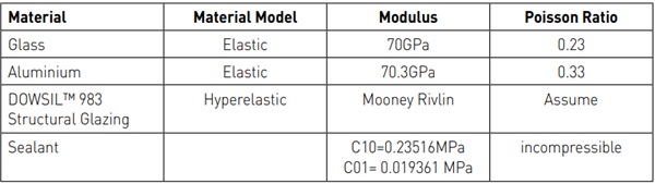
The numerical simulations were performed using a commercial Finite Element Analysis software ABAQUS Due to the assumed incompressible nature of silicone structure sealant, fully integrated hybrid hexahedral elements (C3D8H) were used to prevent element locking, i.e. exhibiting an unphysically stiff response to deformation. The mesh size throughout the sealant thickness has a dimension of 0.5mm, whilst the mesh size of the edge and the glass have a larger dimension of 2.5mm. When relevant, glass, aluminum and structural sealant were modeled in the simulation based on their typical material behavior, as summarized in Table 2. For the bi-component DOWSIL™ 983 Structural Glazing Sealant, the typical design stress in tension is 0.14MPa, in dynamic shear 0.014MPa and in static shear 0.007MPa according to recommended allowable stress found in ASTM C1401. The hyperelastic material model was fully characterized through uniaxial tension, biaxial tension and planar tension testing (Dow 2023).
The sample design 3 was modelled using the assumptions described in Figure 3. Only ¼ of the plate was modelled assuming symmetry boundary conditions.
3. Discussion
3.1. Failure
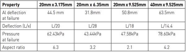
The 4 bonded plates were tested until failure measuring the center of plate deflection and pressure at failure. Table 3 summarizes the experimental results obtained on the various samples of design 3.
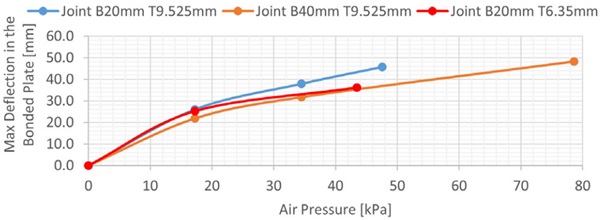
Testing results show a trend that as the bite dimension increases two-fold (from 20mm to 40mm and thickness of 9.525mm), the overall strength of the tested unit does not exactly double, but only increases by a factor of around 1.65. At identical bite, the thickness (AR) also influences the overall strength (pressure at failure) and the deflection at failure as illustrated on Figure 4.
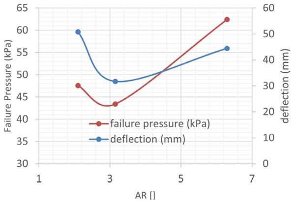
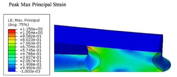
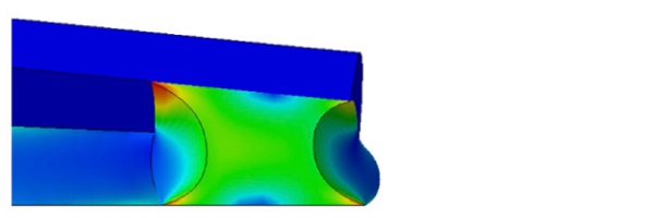
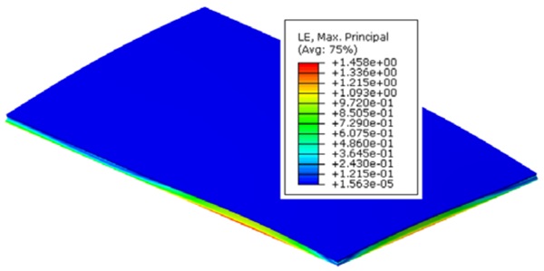
Deflection of tested units shows that as the glueline increases, the deflection at failure trends higher at lower AR (thickness 9.525 mm) versus higher AR (thickness 6.35 mm) indicating increased elongation versus the smaller glueline joint as illustrated by Finite Element Analysis (FEA) of sample design 3, focusing on the joint (figures 5 and 6). Peak principal strains, an output of FEA software that indicate localized areas of maximum strain in the mesh shape and potentially indicate an area of potential rupture, are reported. The maximum principal strain is relatively uniform and in tensile mode for the smaller aspect ratio.
FEA of sample design 3 were run on both 20mm and 40mm bite units with a glueline of 9.525mm and the design of 20mm by 6.35mm to study the deflection at center of plate as a function of joint bite and thickness (Figure 7). Interesting to note is that the deflection values at failure of the joint are extremely high, reaching L/17 for the 20mm x 9.525mm joint and even L/14.5 for the 40mm x 9.525mm joint. These values are only possible because aluminum was used instead of glass. Most glass types used in architectural applications (annealed, heat strengthened, temperature) would likely have broken before failure of the silicone could be reached. Glass thickness is typically designed following industry guidelines, such as ASTM E1300 (ASTM 2016), where deflection generally correlates to being no greater than L/60.
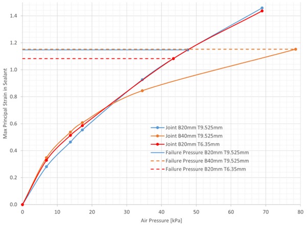
Finally, FEA of sample design 3 determined the peak principal strains corresponding with different unit pressurizations. For all conditions, the peak strain shown in the sealant when the unit reaches experimentally failure was approximately 108-115% for DOWSIL™ 983 Structural Glazing Sealant independent of the aspect ratio (Figure 8). This failure observed on large scale sample corresponds with the peak principal strain recorded on H-pieces when reaching elongation at failure. Care should be taken with these maximum principal strain values at failure.
No statistical evidence has been developed as of yet to understand the influence of batch to batch variation, mixing ratio, or other sources of process variation on the resulting hyperelastic material model characterization. Slight changes in these parameters could lead to variation in maximum principal strain. It is recommended to use a lower value (like 90%) until confidence level for principal strain at failure for DOWSIL™ 983 Structural Glazing Sealant has been increased. The authors are pursuing work to better define this confidence interval. The authors also recommend that complex design results should be discussed with the relevant sealant experts to understand if physical models would be useful for validation.
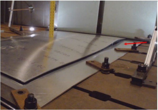
Video recording of the failure origin in the actual testing of the units also correlates with the location of highest peak strains in the FE models of the units. In testing, rupture occurred on the long edge of the unit dimension at a small distance from the corner (figure 9). This is also visualized as the area where the maximum peak strain occurs in FEA (Figure 10). Both observations reinforce that maximum peak strain is a good indicator for failure, as described earlier in (Kimberlain 2019).
The experimental and modeling trends follow observations of the study related to the shape of the joint shown previously (Descamps 2017 and 2018). Glueline thickness, bite dimension and subsequent aspect ratio can influence the overall ultimate strength of the glazed unit due to differences in distribution of stresses due to shape. A lower aspect ratio leads to a higher elongation.
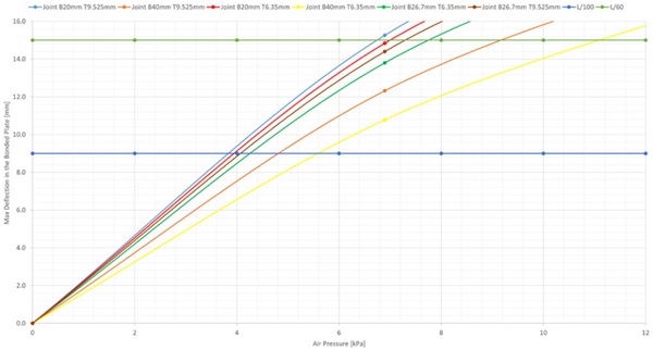
As the above findings have confirmed the possibility to use FEA instead of experimental validation, the behavior of additional joint dimensions (dimensions in Table 4) is modelled to complete the understanding of the SSG under high windload conditions. FEA is used to predict the deflection of the plate for the different joints and the maximum principal strain as a function of the applied pressure. The typical SSG working domain as recommended in ETAG002 limits the deflection of the glass plate to 1% or L/100. For the plate dimensions used in the research, 914mm by 1500mm, this corresponds with a deflection of 9.1mm. Figure 11 shows the maximum deflection in the bonded plate for the different joint dimensions as well as the L/100 and L/60 limits. The air pressure needed to reach the L/100 deflection lies between 4kPa and 6kPa depending on joint dimensions. Similarly, state of the art design of glass (according to quality industry standards such as ASTM E1300) usually corresponds to a limit of the deflection of glass to 1.67% or L/60 which represents 15.24mm for the considered sample and occurs between 7kPa and 11kPa.
Similar to Figure 8, Figure 12 shows the maximum principal strain this time predicted by FEA as a function of the pressure.
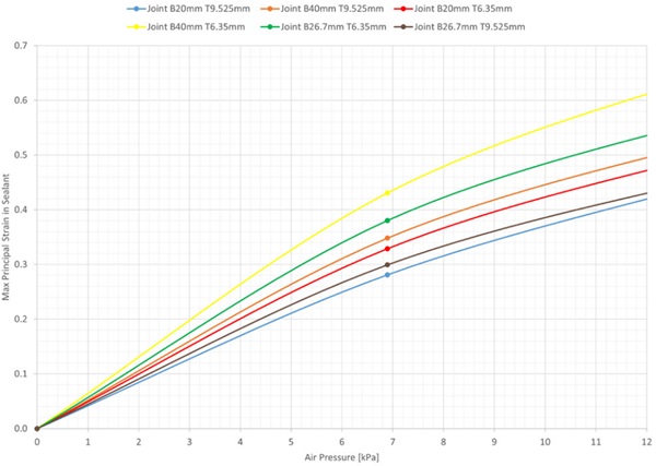
For the sake of clarity, the graph zooms in on the working domain (up to 12kPa) which is of interest for this discussion.
Using the pressures at L/100 and L/60, it is possible to define how much the maximum principal strain is for the different joint designs. These values are reported in Table 4.
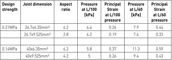
At L/100 deflection, all the joint dimensions have a maximum principal strain of less than 40% which ensures enough durability of the application. At L/60 the maximum principal strains are higher with up to 60% in the case of the highest aspect ratio (40x6mm²). A minimum around 30% is obtained for the lowest aspect ratio.
As an illustration, let’s assume conventional joint dimensioning calculation methods (according to ETAG002 or ASTM C1401) advise to use a joint with 40mm bite for a sealant design strength of 0.14 MPa. The strain experienced by this joint when using a thickness of 6mm is 59% for L/60 deflection/ windloads. This strain can be lowered to 43% by increasing the joint thickness to 9.525mm which can be difficult to accept for the industry.
An alternative is to use higher design strength of 0.21 MPa which will yield a joint dimension of 26.7mm for the bite. The joint of 26.7 x 6.35mm² has a principal strain of 44% at L/60. This is quite similar to the joints of 40 x 9.525mm. To further reduce the strain, increase of thickness to 9mm is possible, which results in a strain of 33%.
This method should not be extrapolated to small joint dimensions, such as 6mm by 6mm. As aspect ratio of joint geometries change from a square to rectangular shape, the pattern of stress distribution diverges from most tensile to a combination of tension and compression. There is also a practical consideration in part as a safety factor related to fabrication. A reduction of 3mm in a poorly applied bite would double the applied stress in a 6mm joint versus 25% in a 12mm joint. Neither is ideal but could occur and further points to a consideration that the higher allowable stresses are suited for larger geometry bites.
3.2. Fatigue Analysis
Structural silicone glazing design is based on an allowable stress predicted from industry standards or wind tunnel simulations. The wind load is expected to occur once in 50 to 100 years. In general, daily exposure for structural glazed applications are much less than the design basis. Mechanical cycle testing from ETAG (EOTA2012) was developed to examine the effect of fatigue stresses on the residual mechanical strength of the sealant bond. The tensile adhesion (TA) joints are therefore exposed to repetitive tensile loads with a cycle time of 6 seconds. The joint is exposed 100 times from 10% to the full design stress des, 250 times from 10% to 80% of the design stress and 5000 times from 10% to 60% of the design stress. This is representative of the spread of windloads in Europe over the lifetime of the joint.
The fatigue test was performed using TA joints with DOWSIL™ 983 Structural Glazing Sealant with joint geometries of different aspect ratios (1, 2, 3 and 4). The design stress was increased from 0.14MPa to 0.21MPa and 0.5MPa. The purpose of the testing was to determine if joint geometry can influence the sealant durability (change of adhesion type) or maximum performance. Therefore, the tensile strength, the maximum elongation and the stress at 12.5% (corresponding with the linear approximation of the modulus) as well as the type of failure (adhesive or cohesive) were recorded. Due to the length of the testing the below results were obtained on only one TA joint. Statistical interpretation with more testing pieces is needed and the described observations should be considered as trends at this stage of the research. The reference data for TA joints of different AR without fatigue have been obtained on 10 samples for AR=1 and on 5 samples for the other AR. The summary of the testing is provided in Table 5.
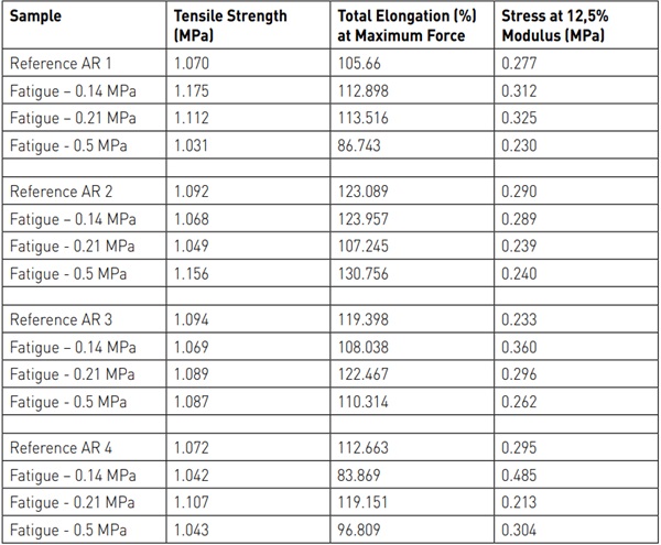
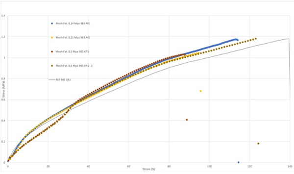
As the design stress increases, the TA joints maintain the same maximum tensile strength (between 1 and 1.2MPa) for all AR. For the same AR, the maximum elongation after fatigue testing seems to decrease slightly as illustrated on Figure 13 for AR=1. Whilst the rigidity of the joint (tensile stress at 12.5%) does not seem to be significantly impacted after fatigue performed at a design stress of 0.21MPa versus 0.14MPa, a significant loss of performance occurs once the design stress reaches 0.5MPa.
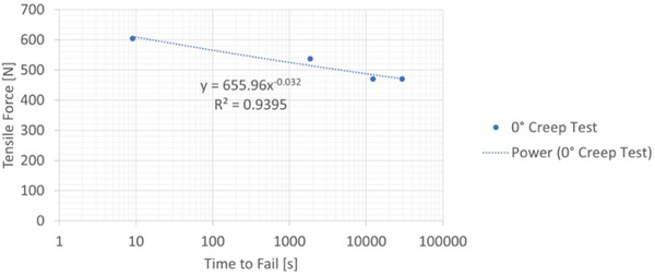
Similar observations can be done for the higher aspect ratios 2, 3 and 4 (not illustrated). Finally, all tested samples maintained cohesive failure even when fatigue occurred. Incorporating the affect of magnitude and duration of loading, useful insights into the behavior of the creep function of sealant can also inform as to an appropriate design stress to maintain durability. Recent research (Kimberlain, 2022) into the effect of orientation of loading onto the stress relaxation behavior of silicone sealant predicts that once the magnitude of the load approaches a significant threshold, the time to failure rapidly increases on a logarithmic scale, see Figure 14. Though the quasi-static testing indicates that the tensile strength at break is in excess of 0.8 MPa, loads approaching 0.67 MPa will fail in days in continuous loading. Factoring in the idea that buildings constantly move and that windloads may be higher in the future, preserving the sealant from excessive loading history to prevent affects of stress relaxation should factor into discussion of fatigue on sealant durability.
This indicates that fatigue behavior should be the limiting factor to the increase of design strength when dimensioning SSG joints for high performance silicone but that 0.21MPa is a safe design value allowing enough safety versus a value leading to damage of the silicone. This also shows that using an even higher design strength of 0.3MPa is close to the fatigue limit which was identified at 0.5MPa. Due to fatigue, it is recommended to not cross the 0.21MPa in design strength.
4. Conclusion/Design Guidelines
Inherent to the proven performance of structural silicone sealants over the last several decades, a proper design must incorporate a sufficient stiffness to withstand normal building exposures such as wind load, but must be flexible enough to accommodate building movements. Principle to design theory, it has been assumed that a conservative approach for dimensioning structural joints will yield a geometry that acts mostly in one direction (tension).
However, structural silicone sealant performance can be influenced by the joint dimensions. As bites increase, distribution of stress changes can impact the potential rupture point. Rigidity of the sealant behavior increases as bites become larger and sealant begins to distribute stresses in a combined manner such as compression and tension versus mostly tension.
For large bites, increasing the allowable stress from 0.14 MPa to 0.21 MPa would have a beneficial effect by making the joint less rigid under normal exposures without sacrificing the overall durability based on FE and fatigue analysis coupled with actual mock-up testing. Also, increasing the glueline thickness can improve distribution of stresses. For purposes of the paper, this begins with an aspect ratio of 2:1 width to depth because shape influences sealant behavior and rectangular shaped joints will have a greater propensity to reflect this combined behavior rather than a purely square dimension. Furthermore, small square joints of e.g. 6mm by 6mm are more challenging from a production point of view. The smallest inaccuracy in application will result in important loss of performance. For similar production accuracy reasons, large aspect ratio should be used with care. It is indeed very challenging to ensure correct application and complete filling of thin and wide joints.
Further, as FEA continues to be utilized in design of structural silicone glazing, the location of peak strains output from a model gives a good indication of the potential rupture point of a sealant and hence an understanding of sealant durability. Further work is needed to understand the statistical relevance of a maximum peak value such as 80% versus 100%. For current design purposes, selecting a reasonable peak strain of around 20% appears to provide a sufficient boundary with sufficient safety factor to prevent rupture.
As assumptions become less conservative on sealant behavior for purposes of extended design possibilities, further increases to sealant allowable stresses could have significant impact to sealant durability. In simple stress-strain curves, hyperelastic sealants tend to inflect from elastic to plastic behavior trending towards the more brittle behavior of the curve. Fatigue analysis demonstrates that loads approach 0.5 MPa can dramatically impact durability based on mechanical cycle testing. Duration and magnitude of loading can also impact durability and time and should be studied as part of discussions to set appropriate design criteria. Further increases beyond 0.21 MPa leave little factor of safety for unintended interactions when using simplified design methods. In general increasing design strength should go together with increased production quality control and guaranteed tolerances.
To summarize, increases to allowable design stress of structural silicone sealants from 0.14MPa to 0.21 MPa should be reasonable for sufficiently shaped joints. Rectangular joints should be considered due to the stiffening behavior due to panel deflection of the composite behavior of a structurally glazed unit. Boundaries of peak strains should be used in FE models as a measure of durability for more advanced models. Further increases to allowable design stress should be studied more in detail to understand how shape and overall unit behavior can impact sealant durability.
5. Disclaimer
THIS INFORMATION IS OFFERED IN GOOD FAITH FOR YOUR CONSIDERATION, BUT WITHOUT GUARANTEE OR WARRANTY (EXPRESS OR IMPLIED), AS ANALYTICAL CONDITIONS AND METHODS OF USE OF THE INFORMATION AND MATERIALS DESCRIBED HEREIN MAY VARY AND ARE OUT OF DOW'S CONTROL. ALTHOUGH THIS INFORMATION IS BASED ON DATA DOW BELIEVES TO BE RELIABLE AND ACCURATE, WE DO NOT INTEND FOR YOU TO USE, AND YOU THEREFORE SHOULD NOT CONSTRUE, THE CONTENTS OF THIS DOCUMENT AS BUSINESS, TECHNICAL OR ANY OTHER FORM OF ADVICE. WE RECOMMEND YOU DETERMINE THE SUITABILITY OF THE INFORMATION AND MATERIALS DESCRIBED HEREIN BEFORE ADOPTING OR USING THEM ON A COMMERCIAL SCALE. DOW ASSUMES NO LIABILITY IN CONNECTION WITH THE USE OF THIS INFORMATION
® ™ Trademark of The Dow Chemical Company ("Dow") or an affiliated company of Dow
6. References
ASTM C1401, Standard Guide for Structural Sealant Glazing (2014)
ASTM E1300, Standard Practice for Determining Load Resistance of Glass in Buildings (20016)
Descamps P.,Hayez V, Next generation calculation method for structural silicone joint dimensioning, Glass Structures & Engineering Volume 2 Number 2, 169-182M.: (2017)
Descamps P., Hayez V., Silicone Joint Dimensioning Calculation Methods, Challenging Glass Conference Proceedings, v. 6, p. 337-350 (2018)
Dow, DOWSIL™ 983 Structural Glazing Sealant Simulation Data Sheet, www.dow.com, accessed 25th April 2023
Drass, M., Kraus, M.A. Dimensioning of silicone adhesive joints: Eurocode-compliant, meshindependent approach using the FEM. Glass Struct Eng 5, 349–369 (2020a). https://doi.org/10.1007/s40940-020-00128-4
Drass, M. & Kraus, M. A. Semi-Probabilistic Calibration of a Partial Material Safety Factor for Structural Silicone Adhesives - Part I: Derivation. International Journal of Structural Glass and Advanced Materials Research, 4(1), 56-68. (2020b) https://doi.org/10.3844/sgamrsp.2020.56.68
EOTA, ETAG 002, Guideline for European technical Approval for Structural Sealant Glazing Kits (2012)
Kimberlain J., Knowles J.A, Investigation of the Impact of Increasing Design Loads of a Conventional Structural Silicone Joint Using Finite Element Analysis and Hyperelastic Material Properties, in, edited by Carbary, L. and Wolf, A. (West Conshohocken, PA: ASTM International, 2015), 1-18. https://doi.org/10.1520/STP158320140063.
Kimberlain J., Carbary L.D., Descamps P., Hayez V., Feng J., Durability of Structural Silicone Sealant in Cold Bent Glazing Design, in Proceedings of Glass Performance Days, pp 2-5 (2019)
Kimberlain J., Hayez, V., Feng J., Mirgon, M., Material Models for Structural Silicone Sealant in Complex Loading, Durability of Building and Construction Sealants and Adhesives: 7th Volume, West Conshohocken, PA: ASTM International, 2022, pg 76-95 https://doi.org/ 10.1520/STP163320200073
Maniatis, I. and G. Siebert. A new design approach for structural bonded silicone joints. Proceedings of the GlassCon Global USA, (IGT’ 16), Innovation in Glass Technology, pp: 159-164 (2016).