Authors: Julian Hänig & Bernhard Weller
Source: Glass Structures & Engineering | https://doi.org/10.1007/s40940-022-00174-0
Abstract
The desire of builders and architects of maximum transparency and homogeneous surfaces in glass façades and glass structures extends to interior all-glass applications such as glass partitions or all-glass doors. In conventional glass systems the interconnections are performed by eye-catching fittings and clamping details that reduce the transparency and disturb the aesthetics. Novel glass–plastic-composite panels show a significantly reduced self-weight by composition of a polymer polymethylmethacrylate (PMMA) interlayer core and cover layers of thin glass.
The innovative composites show high structural performance with optical properties of conventional glass. The panels allow for a direct connection into the thick PMMA interlayer core with the supporting structure or other panels. Such an integrated connection design reduces stress concentrations and allows for the development of small and unobtrusive fittings. Different integrated connections for the glass–plastic-composite panels have been designed and investigated. This article presents an experimental study on different connections, such as mechanically fastened and adhesively integrated, tested under tensile loading. Based on video analyses, crack progressions and failure mechanisms are evaluated and discussed in detail.
The tests investigate temperature effects as well as the influence of the interlayer core thickness and glass type of the cover layers in varying build-ups. The comprehensive evaluation includes a description of the mechanical load-bearing behaviour in form of load versus displacement graphs as well as an investigation of crack progression and failure mechanisms for the final assessment. The results from this experimental study elucidate the structural characteristics of integrated connections in glass–plastic-composite panels under tensile loading and represent a basis for the ongoing development of real application fittings.
Introduction
Motivation and state of the art
Both, high transparency and an economic design due to weight reduction is increasingly becoming a more sought-after characteristic in recent design trends. Designers and engineers focus on lightweight glass façades, glass structures and interior all-glass systems. Glass is known to be a brittle material. It is very sensitive to stress concentrations that primarily occur in conventional point connections such as bolts or clamps. Furthermore, the required mechanical drill hole and the limited area for force transmission accentuate decisive stress concentrations that result in relatively large and obtrusive connections. This motivates to develop novel small and unobtrusive connections with an efficient material-specific design to fulfil the requirements of high transparency and resource efficiency in glass structures.
In the last decades, multiple adhesive connection types have emerged as an alternative to mechanical connections (Centelles et al. 2019). Adhesive bonding with structural polymeric adhesives reduces stress concentrations in the glass and achieves a highly efficient connection design. Transparent stiff structural adhesives such as acrylics, epoxides and polyurethanes were investigated for small sized point connections in different works (Dispersyn et al. 2014; Dispersyn and Belis 2016; Kothe et al. 2016; Tasche 2007; Van Lancker et al. 2016; Vogt 2009; Wünsch 2017).
More flexible structural silicones are often used for linear supports of structural sealant glazing facades but also in a relatively stiff and transparent type for point supports (Drass, 2020). Metal-to-glass laminated connections with different interlayer films achieved high load-bearing capacities depending on the interlayer material (Ioannidou-Kati et al. 2018; Louter and Santarsiero 2019; Santarsiero et al. 2017). Conversely, artificial ageing and temperature changes significantly influence the properties of the investigated thermoplastic polymers. That is why for most adhesively bonded connections in the building industry, the local authorities still insist on cost-intensive and intricate approvals.
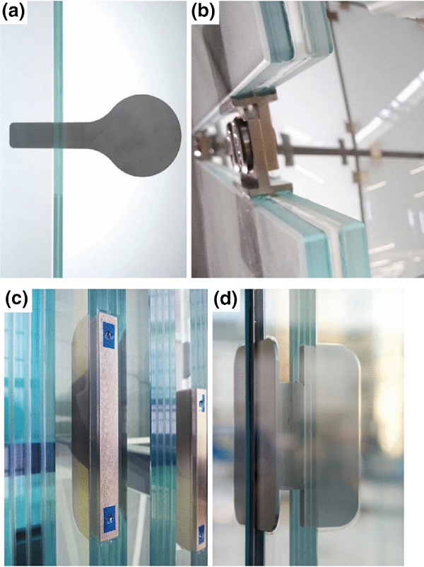
Likewise, embedded laminated connections have been researched in several works (Bedon and Santarsiero 2018; Carvallo, 2014; Feirabend 2010; Neugebauer 2005; Puller 2012; Santarsiero et al. 2017, 2018; Volakos et al. 2021; Zangenberg et al. 2012). The joining technique is known as a metal insert that is encapsulated between a multi-ply glass element by lamination with a structural interlayer film, adhesive or casting resin. This reduces stress concentrations and leads to unobtrusive integrated connection design. Depending on the size and structural interlayer type, these embedded connections exhibit relatively high load-bearing capacities. The research on embedded connections can be separated in thin (Fig. 1a and b) and thick (Fig. 1c and d) insert configurations. Thin inserts are enclosed between only two glass layers, whereas thick inserts require three or more glass layers for integration.
In summary, the idea of integrated connections using metal inserts in laminated glass is applicable and has already been successfully realised in real-world projects (O’Callaghan 2007, 2012; Schieber et al. 2021; Torres et al. 2017; Willareth and Meyer 2011). However, the relatively small interlayer film thickness ranging from 0.38 to 2.28 mm limits the maximum insert thickness as both sides need to be laminated in between two glass plies. First investigations in (Volakos et al. 2021) with a polyurethane based casting resin were performed with an interlayer thickness of 6 mm. Casting resins allow for thicker insert integration compared with conventional interlayer films (Volakos et al. 2021). The thick embedded connections require minimum three layers of glass. This results in substantial self-weight of the glass laminate that consequently limits its application to large-scale glass structures.
Glass–plastic-composite panels
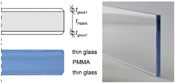
Novel glass–plastic-composite panels, called NEEROGLAS®, consist of a stiff and transparent PMMA interlayer core and thin glass cover layers (Fig. 2). The panels have been developed as a lightweight substitute for current conventional monolithic glass. Previous studies by the authors (Hänig and Weller 2020, 2021) have investigated the material properties of the interlayer core material and evaluated the composite behaviour in a wide range of composite build-ups.
The combination of lightweight PMMA interlayer core with thin glass shows high structural load-bearing performance at reduced self-weight – e.g. an 8 mm/12 mm glass–plastic-composite with 1 mm glass cover layers reveals a reduction in self-weight of 39%/ 44%. At the same time, the cover layers ensure scratch resistance whereas the polymer core provides ductility. The composite panels can be manufactured with an interlayer core thickness of up to 20 mm and all types of cuttable glass cover layers—preferably thin glass with 0.5 to 3 mm thickness (Neeb 2017). A higher panel strength can be obtained by applying chemically strengthened glass (CSG) instead of annealed glass (ANG) as cover layers.
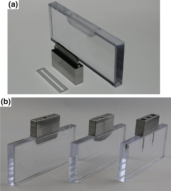
The PMMA interlayer core is higher resistant to impacts and less sensitive to stress concentration in comparison to glass. Furthermore, PMMA allows for conventional mechanical edge processing like drilling and milling as well as polishing for a high-grade finishing quality (Fig. 3a). The introduced properties offer the opportunity for a direct connection to the ductile PMMA interlayer core. The joint can be designed by either a mechanical or an adhesive connection (Fig. 3b).
The glass–plastic-composite panels in combination and a novel integrated connection with sufficient load-bearing performance would offer a structural solution for innovative lightweight glass design. This would generate novel design possibilities for all-glass systems with increased transparency and reduced self-weight. Initial tests showed promising load-bearing behaviour at relatively small dimensions. However, the general load-bearing behaviour and failure mechanism of the integrated connections in glass–plastic-composite panels have not yet been investigated in a wide-ranging experimental study.
As the properties of thermoplastic materials (PMMA and polymeric adhesive) change with temperature (softening at increasing temperature), the load-bearing behaviour is consequently influenced. Furthermore, the build up of the composite panels as well as the distance between the integrated connection and the glass highly affect the stress distribution. This reinforces the need to investigate the performance of such structural connections in order to develop unobtrusive connection hardware for practical applications.
Aim and course of action
Initially, Sect. 2 proposes the integrated connection designs for glass–plastic-composite panels and specimen assembly. Next, the experimental test method (Sect. 3) investigates the quasi-static tensile load-bearing behaviour of novel integrated connections in glass–plastic-composite panels. In the first instance, the application is intended for interior all-glass systems, where high transparency meets unobtrusive elegant connection design. Three different adhesive connection types and one mechanical connection type are considered. The study aims to identify an optimal connection type with high structural performance, easy assembly and high optical quality.
According to these parameters, the connection types have been reduced during the experimental study. In quasi-static tensile testing, the mechanical load-bearing behaviour is evaluated in force–deflection charts (Sect. 4). This includes the examination of initial fracture strength and maximum capacity as an indicator of ductility of the connection. To describe the crack progression and specific failure mechanisms, video recordings during testing were analysed in detail. The wide range of test series at different temperatures and in altering build-ups identify the influencing parameters on the characteristic load-bearing behaviour of the different connection types. The results allowed for comparative discussions (Sect. 5) on the performance of the connection types under tensile loading.
Integrated connection design
The novel edge connections engage with the PMMA interlayer core by employing a mechanical or adhesive connection at the edge of glass–plastic-composite panels. An external stainless steel block, serving as connection hardware, is linked to the PMMA interlayer core of the glass–plastic-composite panel. In both mechanical and adhesive configuration, the PMMA core is processed to accommodate each connection type in corresponding geometrical parameters. To warrant minimal optical obtrusion, the size of the connection was limited to 45 mm length. The minimum distance to the glass cover layers was set to 1 mm for mechanical fastener and 2 mm for the adhesive connection variant. This is intended to limit stress concentrations in the glass through adequate wall thickness of the PMMA for an optimal structural performance.
Mechanical connection
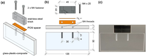
The mechanical connection consists of four main components (Fig. 4a–c): glass–plastic-composite, polyoxymethylene (POM) contact spacer of 1 mm thickness, stainless steel block and two M4 fasteners for rotationally moment fixed connection. Fastener M4 thread profiles were drilled into the PMMA interlayer core of the glass–plastic-composites in a CNC-controlled process. Assembly of specimens was achieved by linking the stainless steel block to the glass–plastic-composite panel with two M4 fasteners in a thread depth of 17 mm. The POM contact spacer was placed between the block and panel edge to avoid unwanted contact stresses between the metal and thin glass. Tightening of the M4 fasteners with a small torque of only 0.3 Nm secures the components without harming the threads in the PMMA or inducing significant pre-stresses.
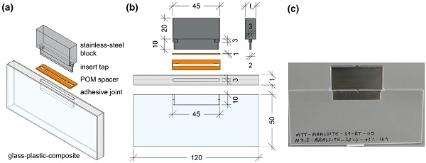
Adhesive connection
The adhesive connections consist of four main components: glass–plastic-composite, 1 mm POM contact spacer, stainless steel insert and adhesive joint (Fig. 5a–c). The stainless steel insert is formed by the exterior block with the 2 mm thick insert tab that is adhesively bonded inside the PMMA core of the glass–plastic-composite. The glass–plastic-composites are mechanically CNC-milled with a 3 mm width and 10 mm depth profile. Laterally arranged alignment taps with a diameter of 3 mm allow for centering of the insert tab within the PMMA interlayer core. The adhesive joint was designed with a gap width of 0.5 mm for the sides and 1 mm at the bottom between the substrates.
This enables the applicability of a wide range of structural adhesives and offers more flexibility at the bottom face of the insert than at the side faces. This is supposed to provide a more intense shear load transfer along the side faces with a larger surface area (2 × 43 mm x 9 mm = 774 mm2) compared to the bottom area (2 mm x 43 mm = 86 mm2) subjected to tension. Chamfered and rounded corners at the bottom face of the stainless steel insert reduce stress concentrations and ensure enclosing with adhesive. After milling of the PMMA joint, all components were carefully cleaned with isopropanol and after complete evaporation filled with the required amount of the adhesive. Subsequently, the stainless steel insert was positioned in the milled profile with the customised intermediary POM contact spacer, held in place and then cured.
A preliminary study of 14 different commercially available transparent structural adhesives was conducted to assess compatibility with the desired adhesive joint. To complement the desire for a less obtrusive connection, an optically clear appearance was a crucial initial parameter in assessing the success of the adhesive. Other parameters included adhesion between stainless steel and PMMA, viscosity, ease of application, curing type and time, shrinkage and imperfections after curing. A reduced pool of viable adhesives was then tested in sun and climate artificial ageing procedures (EN ISO 9142 2004; EN ISO 11431 2003) to assess long-term optical stability of the adhesives inside the composite.
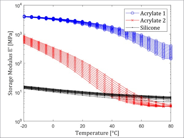
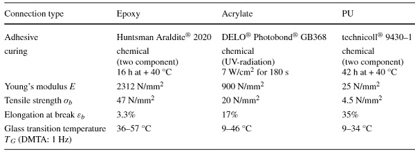
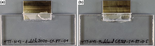
Products that did not develop significant yellowing during artificial ageing were used in the final connection types. This included three different adhesives for investigations: The two component epoxy resin Huntsman Araldite® 2020 (Huntsman Advanced Materials GmbH 2012), the UV curing acrylate DELO® Photobond® GB368 (DELO Industrial Adhesives 2019) and the two component polyurethane technicoll® 9430-1 (Ruderer Klebetechnik GmbH 2018). The applied curing parameters, general material properties and evaluated glass transition temperatures in dynamic-mechanical-thermal-analysis (DMTA) at 1 Hz according to (EN ISO 6721, 2019) of the final adhesive selection are summarised in Table 1.
The selection of adhesives can be classified based on their Young’s modulus and strength into three different classes. A very stiff and brittle epoxy with high strength, a medium stiff acrylate with medium strength and a more flexible polyurethane with lower strength but high elongation at break.
Table 1 Adhesive properties according to (DELO Industrial Adhesives 2019; Huntsman Advanced Materials GmbH 2012; Ruderer Klebetechnik GmbH 2018; Wünsch 2017; Wurm 2007) and unpublished master’s thesis from the Institute of Building Construction, Technische Universität Dresden - Full size table
The selected DELO® Photobond® GB368 was researched in (Louter 2009) for metal-to-glass bonds with intended application in reinforced glass beams (Louter 2011). The structural adhesive exhibited significant bond strength. However, at + 60 °C the strength of the bond was reduced by 55% compared to room temperature. The epoxy Huntsman Araldite® 2020 showed satisfactory performance in terms of bonding strength and ageing for the application in transparent point fixings (Kothe et al. 2016; Wünsch 2017).
The polyurethane technicoll® 9430-1 adhesive was researched in (Kothe et al. 2021) for the application in adhesive joints for thin glass composite panels with 3D printed polymer cores. It proved to be a suitable adhesive for bonding glass-to-polymer in a layer thickness of 1 mm. The joints could be created bubble-free, highly transparent and did not yellow after artificial aging (UV-radiation tests and elevated temperature tests). The properties shown in the published studies confirm the selected adhesives as generally suitable for the proposed application. Nevertheless, since the joining material is PMMA instead of glass and the load transfer is different, an investigation of the novel type of integrated connection is essential for the assessment.
Test methods
Test specimens and study approach
The study approach (Table 2) was designed to characterise the tensile load-bearing behaviour and identify an optimal connection variant. Hence, the selection of connection types is reduced according to their performance during the experimental study. This is discussed in Sect. 4. The first part of the experimental study focused on the temperature effect on various connection types, while the second part explored the influence of the composite build-up on reduced number of connection types.
Table 2 Test series - Full size table
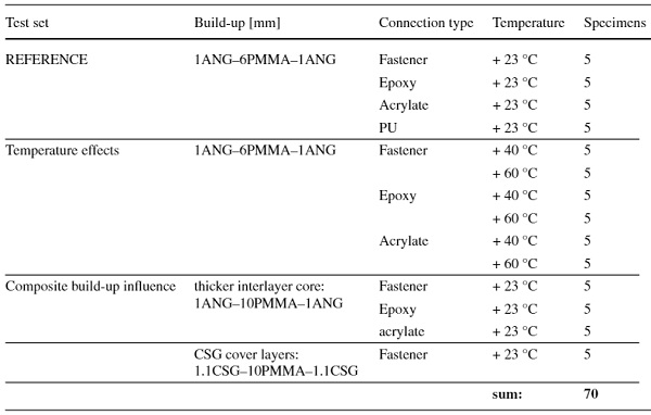
The reference build-up consisted of 1 mm annealed glass (ANG) cover layers and a 6 mm PMMA interlayer core. The edges were waterjet cut with no additional edge treatment. The specimens were tested at + 23, + 40 and + 60 °C to assess the temperature effects up to the upper limit of building industry relevant temperatures according to (EN 16613, 2020) the temperature effects. Lower temperatures are not expected for interior applications. The test series of the second part investigated the influence of composite build-up by testing specimens with an increased PMMA interlayer core thickness of 10 mm. The loaded edge was chamfered (1 mm) and polished. The preferred connection type was additionally investigated by applying chemically strengthened glass (CSG) cover layers with chamfered (1 mm) and polished edge. Altogether, a set of 14 test series with five test specimens each were examined under tensile loading to ultimate failure.
This study approach allows for characterisation of the general load-bearing behaviour and failure mechanisms. Furthermore, the temperature effects and the influence of the composite build-up on the connection performance is explored. The obtained results identify an optimal connection type and represent a basis for the development of real application fittings for all-glass systems in the building industry.
All test specimens were manufactured according to the specifications provided in Sect. 2 and adhesives were cured with the curing parameters according to Table 1. The nominal specimen dimensions amounted to 120 mm × 50 mm, cut to size by waterjet cutting from homogeneous composite panels of 2 m × 1 m and edge processed by an edge grinding machine for glass. The stainless steel parts and POM spacers were mechanically manufactured in high precision by CNC milling.
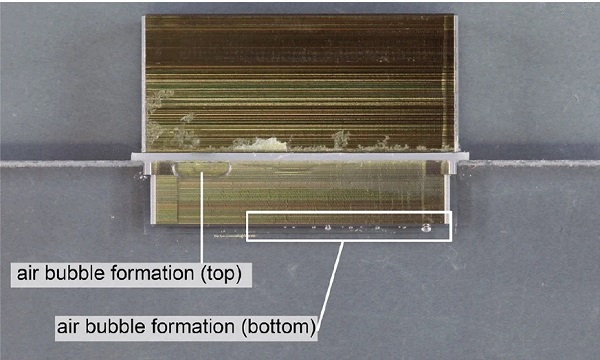
Air was trapped in the resin injection due to mixing and insertion of the stainless steel insert. Hence, relatively small air bubbles were observed, mainly at the top of the side faces and at the bottom, at almost all adhesive connection test specimens after curing (Fig. 6). A repetition of the tests with an automated application rig would allow to minimise inclusions. The small air bubbles influence the visual appearance but due to low ratio of the inclusions compared to the bonded area (< 3%), the bubbles are expected to have no significant influence on the general load-bearing behaviour of the connection.
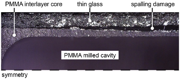
Furthermore, severe spalling issues at the PMMA-glass interface were detected in the milled cavity for the insert profile of the adhesive test specimens (Fig. 7). In a CNC-milling study on parameters of cutting speed, diameter of tool, feed rate and rotational speed, the damage could be minimised. However, spalling damage was still present in all specimens for adhesive connections. The larger distance to the glass in the thicker specimens resulted in a reduction of the spalling intensity. The precise location or cause for the damage remains uncertain; however, successful milling with previous glass–plastic-composite specimens allude to a material cause.
Tensile test setup
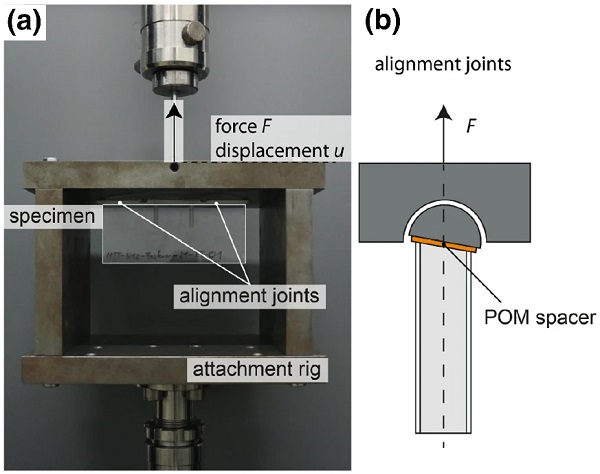
Figure 8a illustrates the tensile test rig used for the experiments. Each specimen was fixed for vertical movement at the custom steel attachment rig. The force was introduced through a universal testing machine (Instron UPM 5881) at a centred M6 thread at the top of the connection metal block. Two alignment joints level the force introduction to ensure pure tensile load at the connection (Fig. 8b). POM sheets in a thickness of 1 mm between the alignment joints and the specimen prevent any steel to glass contact. A temperature-controlled test chamber allowed testing at different temperatures according to the study approach.
Test procedure
All specimens were preconditioned for at least 24 h at the individual test temperature level. The force was induced displacement-controlled with a rate of 0.25 mm/min. The pre-load was set to a force level of 30 N to ensure the alignment of the specimen in the test rig. Force and crosshead displacement were recorded using the measurement cells of the testing machine. During the tests, a video camera recorded the crack development in the specimen in frontal depiction. The tests ended with ultimate failure of the connection by breakage of PMMA interlayer core of the specimen or failure of the adhesive joint.
Evaluation of results
Each test resulted in a value of force F and displacement u. Force–displacement charts describe the load-bearing behaviour of the test series until ultimate failure or until the insert is pulled out at a low load level. The video material during the tests was analysed to evaluate the crack progression and failure mechanisms of the connection by schematic illustration. Based on synchronisation with the force–deflection behaviour, the associated load levels were examined. It should be mentioned that the video analysis was performed manually and hence, includes a subjective character. The illustrated fracture patterns indicate the failure characteristics and loss of integrity of the individual connection type.
To interpret the residual load-bearing capacity of the connection after the initial crack development, the initial fracture loads and the maximum load capacity are examined. Based on the results, the connection types are compared and classified by their structural performance.
Experimental results
The results of the experimental study are presented individually for each connection type. Firstly, the crack progression and failure mechanisms are described by means of schematic illustrations of the typically observed behaviour of a representative test specimen for each connection type at + 23 °C. The focus is set on the relevant observed cracks in the thin glass, the adhesive failure modes and the ultimate fracture of the specimen. Secondly, the temperature-dependent load-bearing behaviour for each connection type is illustrated with comprehensive force–displacement charts. The results for each connection type are plotted in separate diagrams. For a better comparison, all diagrams use the same scales on both x- and y-axis. Subsequently, the strength performance of the individual connection types is described with initial fracture load and maximum load capacity. Thirdly, the influence of the composite build-up on the structural load-bearing performance is evaluated by employing a thicker interlayer core and the use of chemically strengthened glass cover layers.
Crack progression and failure mechanisms
Mechanical fastener connection
The load-bearing behaviour of the mechanical connection is nearly linear (Fig. 9). The initial slope of the force–displacement curve is attributed to the movement of the alignment joints paired with the movements required to fully engage fastener threads with the PMMA material. Initial cracks developed with small rounded crack formation in the thin glass at the threads of the fastener close to the exterior stainless steel block having no influence on the load-bearing behaviour (stage 1).
Following stage 1 fracture, crack formation spreads along the length of the screw inside the thin glass as glass offers reduced fracture toughness compared to the PMMA interlayer core that remains intact (stage 2). Only minor deviations from linear load-bearing behaviour were observed until stage 3 fracture with rounded crack development, which propagate with increasing force at the end of one screw. This generates an interim drop in force. The ultimate failure occurs by sudden rupture of the glass–plastic-composite starting at the end of the thread, splitting the specimen.
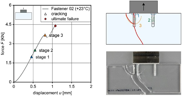
The initial fracture in stage 1 occurs due to the increased stress concentration within the first few engaged threads of the fastener (Fakhouri et al. 2014; Kloos and Thomala 2007). Subsequent crack formation in stage 2 can be explained by the similar force transfer phenomenon in deformed rebars for materials such as concrete, where the compression bearing of angled ribs along the bar are used to transfer tensile forces. This radial compression struts induce a balancing tension ring of stress in the encapsulating material (Tepfers 1976) that causes the stage 2 fracture. The ultimate failure can be attributed to concentrated stresses at the end of the threads leading to tensile crack development (stage 3), which increases towards ultimate failure with crack propagation, until the fracture of the PMMA. However, the thread remained intact and showed no signs of damage until the ultimate failure.
Adhesive epoxy connection
The adhesive epoxy connection exhibited a stiff behaviour until brittle failure (Fig. 10). Due to its high Young’s modulus (Eepoxy = 2312 N/mm²), the PMMA and epoxy are similarly stiff (EPMMA = 2337 N/mm²). This results in glass cracking perpendicular to the tensile load, as the insert behaves as fully embedded in a uniform material. Preliminary cracks in stage 1 were typically located in the thin glass layers, at the ends of the inserts. Cracks gathered in a similar location as the insert tab was pulled out, after which new cracks in the thin glass appeared near the bottom edge of the insert (stage 2). The subsequent cracks identified in stage 3 originated with the bridging and propagation of earlier cracks. This was closely followed by a complete fracture of the glass–plastic-composite along the arched fracture line created by previous cracking.
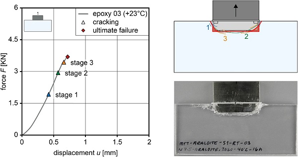
The connection’s insert tab disengaged from the glass–plastic-composite section along the fracture line, but it was not removable due to crack bridging in glass, or incomplete cracks through the PMMA. The portion of the glass–plastic-composite and adhesive joint above the failure crack line remained mostly undamaged and still firmly adhered to the stainless steel insert.
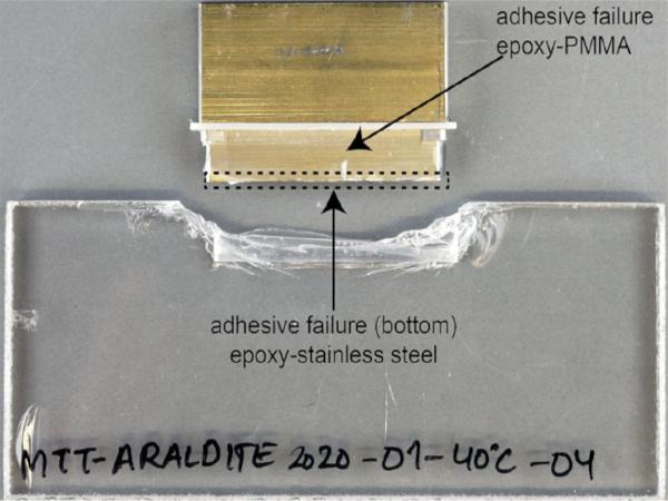
Location of adhesive failure is visualised by the red shaded region in Fig. 10 and was observed along the crack line. The loss of adhesion at the bottom occurred at the epoxy-stainless steel interface at rupture, whereas adhesive failure modes at the faces were observed in the epoxy-PMMA interface. This allowed for the release of the insert tab from the glass–plastic-composite during ultimate failure. Furthermore, partial cohesive failure was observed along the bottom crack line by partial pull out of the stainless steel insert.
Adhesive acrylate connection
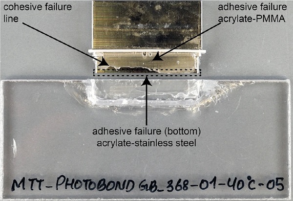
The adhesive connection with the acrylate joint exhibited linear behaviour until the point of ultimate failure (Fig. 11). Initial cracks (stage 1) of the acrylate specimens were observed in the thin glass along the bottom line perpendicular to the load. In stage 2, the cracks were located at the edges of the inserts and did not extend past the perimeter of the adhesive joint. Striations developed in stage 3 at the adhesive faces of the insert indicating adhesion loss on both PMMA and stainless steel interfaces. Soon after stage 3, the adhesive suddenly failed in a cohesive failure mode. The test specimen remains largely intact.
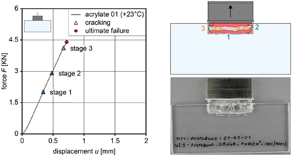
The failure in the adhesive appeared in all specimens on at least one of the insert faces. At rupture, fracture at the glass surface was increased substantially. This may be attributed to the quick displacement of the insert tab as it is suddenly pulled out at ultimate failure. The insert still sticked to the glass–plastic-composite after testing. The observed failure mechanisms indicate ultimate failure of the joint caused by the lack of strength of the acrylate.
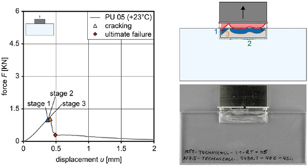
Adhesive PU connection
The tensile behaviour of the adhesive PU connection denotes increased flexibility (Fig. 12). The failure sequence began with adhesive failure at the adhesive-PMMA interfaces indicated by the loss of clarity (stage 1). Subsequent cracking of the thin glass along the bottom side of the insert (stage 2) perpendicular to the force was observed. Stage 3 followed shortly with a cohesive failure of the adhesive at the boundary line created by the area of adhesive still in contact with the PMMA walls. The cohesive failure did not instantaneously lead to ultimate failure due to low force levels. Instead, the failure gradually progressed from stage 3 to ultimate failure by almost complete tearing.
During this transition, the intense tear correlated with nearly full loss of connection resistance. The residual load capacity within the force–displacement curve captured the gradual sliding of the insert out of the PMMA cavity and was not of significant importance as the connection was considered to have reached ultimate failure at the apex of the force–displacement curve. Overall, the low stiffness of the adhesive and early adhesive failure resulted in minimal fracture of the glass–plastic-composite specimen during testing.
Temperature dependent load-bearing behaviour
The unified force–displacement charts (Fig. 13a–d) of the test series characterise and compare the load-bearing behaviour of the investigated connection types at different temperatures. The strengths of the connections and corresponding statistics are discussed in Sect. 4.3.
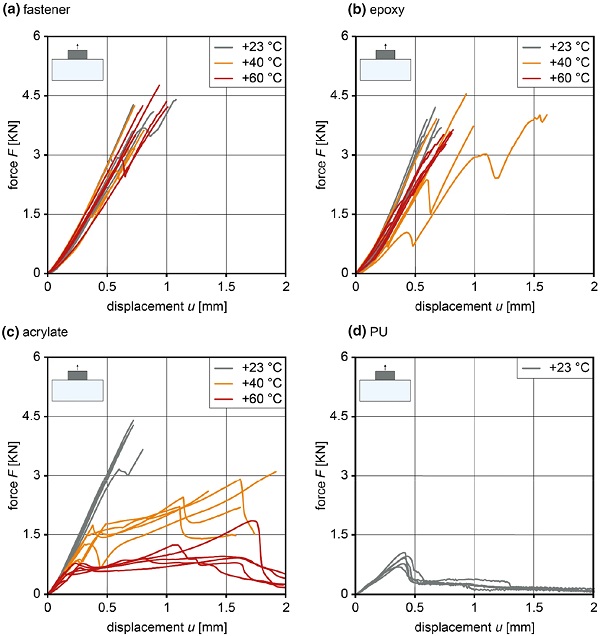
Mechanical fastener connection
The test series of the mechanical fastener connection at + 23, + 40 and + 60 °C represent a linear load-bearing behaviour (Fig. 13a). Individual specimens only showed crack developments at a force level between 2 and 4 kN that resulted in a significant drop in force, followed by a further increase in load leading to ultimate failure. The ultimate force level characterizes the final failure and maximum capacity load of the PMMA interlayer core.
Adhesive epoxy connection
The adhesive epoxy connection exhibited a linear behaviour until sudden failure (Fig. 13b). At + 40 and + 60 °C, an increasing scatter between the individual tests was observed. The specimens developed significant cracks at the edges leading to earlier partial loss of adhesion at epoxy-PMMA interface on the side faces of the insert (Fig. 14). In general, even at + 40 and + 60 °C, the epoxy adhesive exhibited high stiffness however, paired with adhesion loss at the interface with the PMMA interlayer core at lower load levels.
Adhesive acrylate connection
Significant temperature dependence of the adhesive acrylate connection can be observed in the force–deflection charts (Fig. 13c). The adhesive softens already at + 40 °C due to relatively low glass transition temperature (9–46 °C). This leads to increased displacements until ultimate failure. Adhesive failure modes were detected between acrylate and stainless steel at the bottom of the insert and between the acrylate and PMMA on the side faces (Fig. 15). At + 60 °C, limited force transfer is observed. This is due to yielding of the adhesive joint after which the insert is pulled out at relatively low force level with similar failure modes as described in Sect. 4.1.
Adhesive PU connection
The adhesive PU connection exhibited lowest stiffness compared to the other adhesive joints (Fig. 13d). This is in agreement with the material properties in Table 1. The glass transition temperature (9–34 °C) is around room temperature. Therefore, at elevated temperature even lower stiffness and capacities due to increased softening of the adhesive are anticipated. This directed the exclusion of the adhesive for further testing.
Comparison of strength
The evaluated results of the first test series (Fig. 16) allow for a comparison in strength with corresponding statistics. It includes the initial fracture load and maximum load capacity of the connection. The post-fracture load reserves (marked by the arrows) are evaluated as the additional capacity up to the maximum load capacity after the initial fracture load. This quantification can be employed in fail-safe design concept for practical applications. The complete statistics of the individual test series are summarised in Table 3.
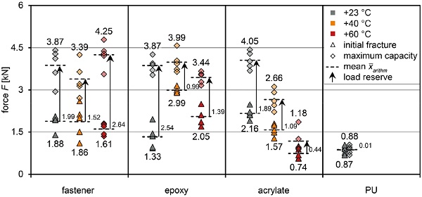
Table 3 Strength results of the connection types from experimental tensile tests at different temperatures. (arithmetic mean x̅arithm ± variance σ2; change (x̅−x̅ref)/x̅ref); post-fracture load reserve) - Full size table
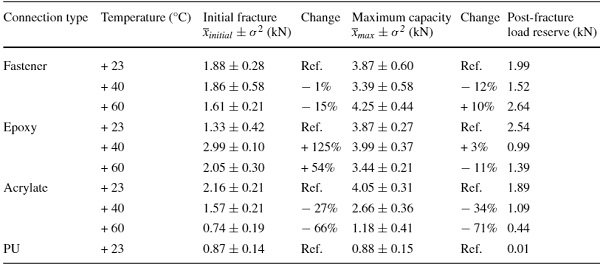
The strength of the fastener remains in the same order of magnitude for all tested temperatures (maximum change of -15%). This confirms consistent load-bearing behaviour that can be attributed to the relatively low change in Young’s modulus of the PMMA interlayer core at temperatures up to + 60 °C. Amongst adhesive connections, adhesive stiffness, strength and adhesion were the main parameters dictating the initial fracture and strength. In general, the lower the adhesive stiffness, the lower the overall strength of the connection regarding both initial fracture load and maximum load capacity.
This influence of adhesive stiffness is clearly visible for the acrylate connection by the reductions of -66% for initial fracture and -71% for maximum load capacity caused by temperature effects. At + 23 °C, the rigid epoxy showed lower initial fracture strength (1.33 kN) than the more flexible acrylate (2.16 kN). It can be concluded that the adhesive joint requires a certain level of flexibility to reduce stress concentrations in the thin glass of the composite that is decisive for the initial glass fracture. At + 40 °C, the epoxy connection attained the highest overall initial strength of 2.99 kN representing an advantageous balance of stiffness and strength. At + 60 °C, the strength decreases to 2.05 kN due to earlier initial fracture formation. The low stiffness and tearing of PU resulted in very poor overall performance (initial fracture: 0.87 kN and maximum capacity: 0.88 kN).
All connections, except adhesive PU connection, show an increase in load capacity following the initial fracture. Hence, post-fracture load reserves ranging from 1.52 to 2.64 kN for fastener, from 0.99 to 2.54 for epoxy and from 0.44 to 1.89 kN for acrylate connection were quantified (Table 3). The PU adhesive connection did not offer noteworthy load post-fracture load reserves due to tearing of the adhesive.
Influence of composite build-up
The influence of composite build-up is represented in similar strength comparison (Fig. 17 and Table 4).
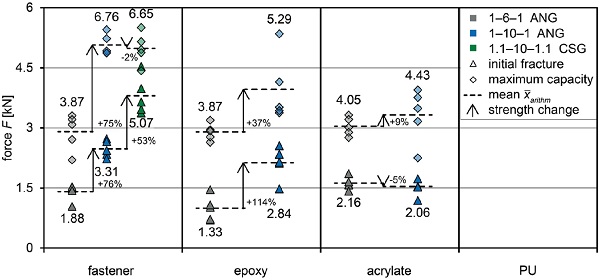
Table 4 Strength results of the connection types from experimental tensile tests for different build-ups at + 23 °C. (arithmetic mean x̅arithm ± variance σ2; change (x̅−x̅ref)/x̅ref); post-fracture load reserve) - Full size table
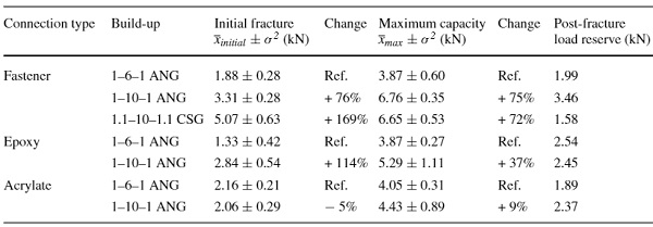
The mechanical fastener connection shows an increase in initial fracture load of + 76% and maximum capacity of + 75%. The failure characteristics match the aforementioned ones for the thinner build-up however, at increased load levels.
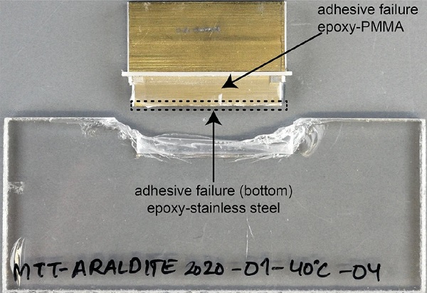
The adhesive epoxy connection shows a significant strength increase (initial fracture load + 114% and maximum load capacity + 37%), whereas the adhesive acrylate connection shows equivalent performance to the thinner build-up (initial fracture load -5% and maximum load capacity + 9%). The initial failures for both adhesives matched the aforementioned characteristics of the thinner build-up. The increased initial strength of the adhesive epoxy connection and low amount of cracking in the test specimen demonstrated a reduction in glass stresses. However, the ultimate failure occurred mainly due to adhesion loss (Fig. 18a). The acrylate adhesive connection failed by mixed adhesive and cohesive failure (Fig. 18b). This justifies the limited increase in maximum load capacity for both adhesive connections, as the load-bearing capacity of the joint becomes decisive.
Overall, the mechanical fastener connection demonstrated superior performance compared to the adhesive connection types, regarding both initial fracture load and maximum load capacity. Hence, the choice of the preferred variant belonged to the mechanical connection and additional testing with chemically strengthened thin glass (1.1CSG–10PMMA–1.1CSG) was carried out.
By the use of chemically strengthened glass, the initial fracture load was enhanced by additional + 53% compared to annealed glass (+ 169% compared to 1ANG–6PMMA–1ANG) whereas the maximum capacity that is defined by the PMMA strength remained at an equal level (Table 4). An initial fracture load of 5.07 kN and ultimate load capacity of 6.65 kN were reached with the mechanical fastener connection leading to a high strength relatively to the small connection and offering a noteworthy post-fracture load reserve. This evaluation quantifies the influence of the glass build-up and the use of chemically strengthened glass cover layers on the strength of glass–plastic-composite panel connections.
Discussion of results
Substantial differences in load-bearing resistance were observed between the different connection types. The adhesive stiffness, tensile strength and adhesion were the main variables dictating the failure modes and maximum capacities of the adhesive connections. The epoxy behaved stiff, but it showed early crack developments in the thin glass. Thicker interlayer core led to a better stress distribution resulting in higher connection strength. In the thin specimens (1ANG–6PMMA–1ANG), the ultimate failure occurred by rupture at the insert whereas at the thick specimens (1ANG–10PMMA–1ANG), adhesive failure was decisive. Hence, the connection offers a high post-fracture load reserve of 2.54 kN (reference) and 2.45 kN (thicker interlayer core).
The acrylate, as medium stiff adhesive, was able to distribute stress concentrations uniformly leading to high initial fracture strength and maximum capacity that leads to consistent post-fracture load reserve of 1.89 kN (reference) and 2.37 kN (thicker interlayer core). The flexible PU adhesive failed early by tearing and pulling out the insert with no post-fracture load reserve. In conclusion, a particular degree of Young’s modulus is required to show sufficient connection stiffness but also limit the stress concentrations in the glass cover layers. The adhesive strength and adhesion specified the ultimate failure mechanisms (adhesive and cohesive failure) of the joint.
High strength paired with sufficient adhesion caused final sudden splitting of the specimen whereas at low strength or insufficient adhesion the insert was pulled out. As the stiffness and strength of the tested polymer adhesives decrease significantly above glass transition temperature, the connections weakened when the glass transitions were transcended and the inserts were pulled out after exceeding the strength. The thicker interlayer core led to higher initial strength of the epoxy connection (+ 114%) due to reduction of glass stresses. However, the maximum capacity was increased to a limited degree only (+ 37%), as adhesion loss and cohesive failure of the joints were predominant. Hence, the strength of adhesive joint limited the maximum load capacity of the connections in build-ups with thicker interlayer core.
Different mechanical connection arrangements were not assessed, while the proposed fastener connection showed nearly linear load-bearing behaviour until ultimate failure. The behaviour is influenced to a limited degree by early fine glass cracks until ultimate fracture of the PMMA interlayer core starting at the end of one thread. Hence, the connection offers a high post-fracture load reserve after initial fracture of minimum 1.58 kN. Furthermore, only insignificant temperature dependency was observed (Fig. 16 and Table 3). This fits to the investigations of the PMMA interlayer core material in (Hänig and Weller 2021). A thicker composite build-up was found to increase the load-bearing performance but not influencing the failure mechanisms of the connection. In total, a more uniform stress distribution by employing a thicker interlayer core increases the connection strengths in both, the initial fracture and maximum load capacity while offering satisfactory high post-fracture load reserves.
Considering the manufacturing or rather the assembly process, mechanical connections exhibited three main advantages over adhesive connections: firstly, the manufacturing of specimens only requires threads in the PMMA that are easier to execute and no spalling defects occur. Secondly, the time of assembly takes only minutes compared to curing times in hours or even several days for the two component adhesive connections. Only the UV-curing acrylate offers a manufacturing time in the range of minutes, however, requiring UV-lamp equipment. Thirdly, the mechanical connection can be disassembled and allow for the reuse of components as well as a quick replacement in case of damage. These key features should be taken into account in the further development process of the connections.
The results for all connections included remarkable scatter of the force levels for initial fracture load as well as maximum load capacity (Table 3 and 4). Highest variance was observed in fastener followed by epoxy connection type whereas the acrylate and PU showed a general higher agreement within the individual test results. The scatter may be attributed to the spalling defects in the proximity of the PMMA and glass interface. Scattering is also influenced by manual assembly, variance in glass thickness as well as surface damage in glass due to processing and handling of the specimens, which influence the glass strength.
Additionally, the sub-critical crack growth development in annealed glass over time due to relatively long load duration influences the glass strength (Brokmann et al. 2021; Haldimann et al. 2008). Different load-durations also influence the stiffness and strength of the viscoelastic adhesive joints. To fix the spalling issue, a change in material composition combined with improvements in polymerisation of the interlayer core as well as tempering are proposed. Furthermore, more consistent assembly practices or an automated manufacturing should be investigated to diminish its influence on the bonding process and to improve optical quality.
Conclusions and outlook
The paper investigated the performance of structural connections in glass–plastic-composite panels as the basis for the development of unobtrusive connection hardware. This includes the detailed examination of load-bearing behaviour, including crack progression and failure mechanisms, of the proposed innovative connection types under tensile loading. The temperature effects and influence of composite build-ups were evaluated in a wide ranging study. For final assessment, the initial fracture load and maximum load capacity characteristics are considered.
Mechanical fastener connections possessed the capability to reach high strength, offering linear load-bearing behaviour that is insignificantly temperature dependent and provide satisfactory post-fracture load reserves. Highest profit (increase of initial fracture load and maximum failure capacity) by increasing the polymer core thickness was observed. It was also found that the glass strength is crucial for the initial fracture resistance but not the ultimate failure load. In general, the mechanical fastener connections allow for a fail-safe design.
The adhesive connection characteristics are dictated by the stress distribution in the glass cover layers, which is highly influenced by the composite build-up, the stiffness and strength of the adhesive. Hence, the stiff (epoxy) and the medium stiff (acrylate) adhesive produced a balance of features in high initial fracture strength and force transferring capabilities up to ultimate failure. This quantifies satisfactory post-fracture load reserves. However, the temperature dependent material behaviour of the adhesives influenced the connection performance significantly resulting in low load-bearing capacity above the glass transition temperature of the adhesives. This limits the application temperatures below the glass transition temperature. The PU connection behaved very flexibly due to low adhesive stiffness. Additionally, the lower adhesive strength led to premature adhesive failure at a comparatively low level of load. This proves the PU as not suitable for the proposed integrated connection.
Preferable load-bearing characteristics, high strength and satisfactory post-fracture load reserves under quasi-static tensile loading identify the mechanical connection type as preferred connection variant. Furthermore, the appealing integrated design with minimal obtrusion as well as a simple and consistently successful assembly makes the connection most appropriate under tensile loading.
The obtained results represent a first comprehensive dataset. However, further investigations are essential to suit practical implementation in glass constructions for the building industry. Therefore, it is suggested to evaluate the load-bearing behaviour under shear loading next as well as under bending and compression in the following steps. Likewise, the long-term stability needs to be investigated for structural use. This will lead to a complete dataset for the structural design of connections for the glass–plastic-composite panels. Current research deals with these structural characteristics and will be published in upcoming articles.
In order to limit experimental studies, accompanying numerical analysis and a broader parameter study are proposed for connection optimisations. This needs to include the detailed stress distributions as well as the investigation of influencing parameters such as composite build-up as well as inserted depth and size of connection. The collected dataset of this research, including force–displacement charts and the understanding of crack progression and failure mechanisms, will contribute to the validation of numerical models. On this basis, structural connections can be reliably designed according to its application and adapted for best load distribution. The integrated connection designs for lightweight glass–plastic-composite panels may allow for a more spectacular glass design meeting high transparency with lightweight design in the future.
References
Funding
Open Access funding enabled and organized by Projekt DEAL.
Author information
Authors and Affiliations
Institute of Building Construction, Technische Universität Dresden, August-Bebel-Straße 30, 01219, Dresden, Germany
Julian Hänig & Bernhard Weller
Corresponding author
Correspondence to Julian Hänig.
Ethics declarations
Conflict of interest
On behalf of all authors, the corresponding author declares that there is no conflict of interest.