Authors: Simone D’Amore, Simona Bianchi, Jonathan Ciurlanti & Stefano Pampanin
Source: Bulletin of Earthquake Engineering (2023) 21:2657–2689, Springer Nature
DOI: https://doi.org/10.1007/s10518-023-01622-0
Abstract
In the last decades, recent earthquakes have further highlighted the high vulnerability of non-structural components. Post-earthquake damage due to building envelope, equipment and building contents can lead to substantial economic losses in terms of repair costs and daily activity interruption (downtime). Moreover, non-structural damage can represent a life-safety threat for both occupants and pedestrians. These considerations confirm the crucial need for developing low-damage systems for either structural or non-structural elements. This paper aims to assess the seismic performance of glazed facade systems, widely adopted in modern buildings, focusing on point fixed glass facade systems (PFGFSs), also referred to as “spider glazing”. In this work, a numerical investigation is developed to study the seismic performance of such systems at both local-connection level through a 3D FEM in ABAQUS as well as at global system level through a simplified lumped plasticity model in SAP 2000 to assess the overall in-plane capacity of the facade. Based on the local connection and global facade system behavior, a novel low-damage connection system is herein proposed, and a parametric study is carried out on the key parameters influencing the facade capacity. The benefits of implementing low-damage connection details are highlighted by an increase of the in-plane capacity of the facade system when compared to a traditional solution. To further investigate the potential of the proposed low-damage details in preserving the integrity of the facade system itself, non-linear time history analyses have been carried out on a case-study building equipped with the innovative PFGFSs.
1 Introduction
In the last decades, post-earthquake reconnaissance reports have further highlighted the high vulnerability of non-structural components. Damage related to these building systems (architectural elements, mechanical and electrical equipment, contents) can represent a threaten to Life-Safety for both occupants and passers-by. Moreover, non-structural components can highly contribute to increase the building repair costs and the business interruption, even for low-to-moderate seismic intensity levels. Several research studies have highlighted the importance of investigating the seismic behaviour and expected damage mechanisms of non-structural components and contents as well as of including them in the seismic assessment/design/loss analysis of buildings, in consideration of the large investment (82%, 87% and 92% of the total building cost for offices, hotels and hospitals, respectively) associated to non-structural systems in construction (Taghavi and Miranda 2003). Further, O’Reilly et al. 2018, pointed out that for typical school buildings in Italy, most of the direct monetary losses induced at more frequent levels of ground shaking, are associated to non-structural components (> 60%). Moreover, such a high value for (construction and repair costs of) non-structural components could further increase in case of glazed facade. Glazing systems are currently among the most expensive solutions for facade systems. Figure 1 presents several examples of post-earthquake non-structural damage to glazed facade observed during the 22nd February 2011 Christchurch earthquake, New Zealand (Baird et al 2011a).
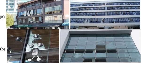
Glazing facade systems are growing in interest due to their elegance, and therefore to their significant impact on the building aesthetics. Usually, glazed facade consists of a framed system, also known as stick curtain walls, composed of mullions and transoms (Fig. 1a). A relatively novel system is the Point Fixed Glass Facade System, PFGFS, which provides greater transparency and elegance (Fig. 1b). From a seismic point of view, such systems should be mostly considered as drift-sensitive, with limited -albeit not negligible in the absence of more data based on dynamic experimental tests- acceleration-sensitive characteristics. For this reason, as part of a seismic/loss assessment of a whole building system it would be appropriate to verify that the imposed drift demand is lower than the in-plane capacity of the facade.
Several research efforts related to stick curtain walls have been carried out in the past years, considering both experimental and analytical studies (Behr et al. 1996, 1998; Memari et al. 2003, 2004). Following these studies, ASCE 7–10 (ASCE 2010), provides an expression to compare the seismic in-plane capacity of framed glass facade and the drift demand. In more recent times, other authors have addressed the problem of the seismic performance of such systems (Caterino et al. 2017; Aiello et al. 2018, 2019; Casagrande et al. 2019). In these works, experimental and numerical studies have been carried out. Refined non-linear Finite Element Models have been developed and benchmarked against experimental results.
Despite the growing interest in PFGFSs, due to their enhanced transparency and elegancy, there are few research works related to this system when compared to more traditional framed glass facade systems. A research project has been undertaken at the Swinburne University of Technology (Sivanerupan et al. 2010, 2014a, b). In this work, experimental tests on two full-scale specimens have been carried out, and numerical predictions with refined Finite Element Models have been benchmarked against the experimental results. This research effort confirms the lower vulnerability of PFGFSs when compared to traditional framed glass systems. Nevertheless, even if PFGFSs are capable of under-going low-to-moderate earthquakes with negligible or minor damage, they could suffer heavy damage for moderate-to-severe earthquakes, Fig. 1b.
Building on the recent focus in the past decades on the development and implementation of low-damage solutions for both structural and non-structural components of a building system (Pampanin 2012, 2015, 2020), a dedicated effort and focus on glazed systems is urgently required, in consideration of their high costs and increasing use. In recent years, several research efforts have been carried out to assess the in-plane and out-of-plane capacity of non-structural components as well as to develop innovative solutions. At the University of Canterbury, New Zealand, different typologies of low-damage non-structural components have been proposed and investigated, i.e. interior drywall partitions (Tasligedik et al. 2015), masonry infill walls (Tasligedik et al. 2017) and heavy cladding systems (Baird et al. 2013). In the case of ceilings, different solutions can be adopted to reduce the expected damage. Pourali et al. (2017), have proposed a fully floating ceiling introducing an elastic isolation foam along the perimeter of the ceiling itself. This limits the pounding effect, reducing the accelerations and displacements onto the ceiling components, and negligible damage is expected. In Europe, two main projects are acknowledged:
(1) The SERA Project, aiming at the study of the overall seismic behavior of an integrated low-damage building system, consisting of innovative structural and non-structural components, by tri-dimensional shake-table tests of a scaled two-storey building prototype at LNEC laboratory in Lisbon (Pampanin et al 2019; Bianchi et al. 2021).
(2) the INSYSME project, aiming at the proposal of low damage systems in terms of seismic performance, whilst also accounting for their energetic and acoustic behaviors. During this project, a novel system for hollow-core clay brick infill walls has been proposed at the IUSS University of Pavia, Italy (Morandi et al. 2018).
2 Objectives and methodology
The main objective of this paper is to investigate the in-plane seismic performance of PFGFSs currently available in the market, and to propose an innovative solution able to reduce the expected damage and enhance the seismic performance under moderate-severe earthquake events. At first, a brief description of PFGFSs is given, focusing on the seismic performance and damage of such facades as observed from past earthquakes as well as to the connection typologies currently available in the market. Then, a detailed Finite Element Modelling is implemented in ABAQUS (ABAQUS Inc. 2011) to investigate the local (connection-level) of such building envelope type. This refined modelling allows to define a macro-model of the facade, consisting of non-linear springs, frame and shell elements describing the in-plane capacity of the overall system.
Thus, a simple and practical numerical lumped-plasticity model, alternative to a micro- and more complex 3D FEM model, is developed in SAP2000 (CSI 2014) to study the seismic performance of PFGFS as part of a frame system. A comparison between traditional and innovative connections is carried out in order to investigate the benefits of implementing low-damage detailing to increase the in-plane capacity of PFGFS. Also, several parametric analyses are performed to assess which parameters mostly influence the in-plane capacity (connection type, number and aspect-ratio of the glass panels, thickness of the silicone weather sealant joint). Finally, Non-Linear Time History Analyses (NLTHA) are carried out in Ruaumoko 2D (Carr 2003) considering a case-study building located in a high seismic prone area of Italy (Amatrice, RI) and comprising glass facades with the proposed innovative low-damage connections.
3 Description of PFGFSs
3.1 System components
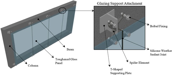
An accurate description of PFGFS is provided by Inca et al. (2019). Such facade system consists of four elements: the main supporting structure, glazing support attachments, bolted fixings, and glass panels. Several typologies of the main supporting structure are available. They consist of a light metallic frame system to support the glass panels. It is worth noting that using such a component is not mandatory. In the absence of a supporting frame, the glazing support attachments are directly connected to the building structure itself and larger glass panels are used. This allows for a greater transparency of the facade, but as a counterpart, larger glass panels become more vulnerable to in-plane movements (Sivenerupan 2010). Figure 2 shows a scheme of PFGFS without the main frame supporting structure.
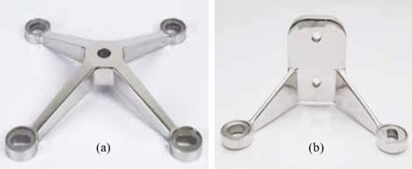
Glazing support attachments allow the transfer of load to the supporting structure or building structure itself. Focusing on the spider elements, either pinned X-Type (Fig. 3a) and fixed K-Type (Fig. 3b) are available. These elements have specific detailing leading to a different capacity in accommodating the in-plane movement of the glass facade.
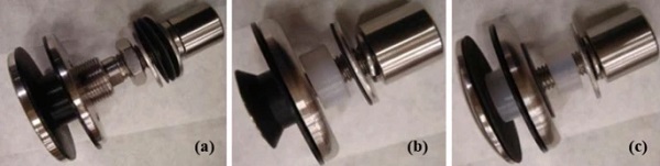
Several bolted fixings are currently available in the market. The main difference between typologies is related to their capacity in transferring the load from the glass panels to the glazing support attachments. The bolted fixings are located nearby the corners of the glass panels. If an articulated bolted fixing (spherical joint) is used (Fig. 4a), a greater rotation and displacement of the panel to the fixing can be accommodated, without causing excessive stress concentration. When either countersunk bolts (Fig. 4b) or button head bolts (Fig. 4c) are used, the out-of-plane and in-plane loads are transferred through the bolt to the glass interface. In these latter cases, the fixing system is less performing.
Regarding the glass panels, toughened or laminated glass is generally used. In the first case, a crucial issue is associated with the potential fragmenting in small pieces in case of rupture. In the latter case, glass is more resistant due to two or more layers bonded together by an intermediate polymeric intralayer, generally PVB (polyvinyl butyral). Yet, this high resistance (overstrength) could affect the correct hierarchy of strength (Baird et al. 2011b; Diaferia et al. 2011) in the facade system: should the glass not be the “weakest link” in the facade system “chain”, a local connection failure could occur, with the fallout of the entire glass panel, resulting in a significant life-safety threat.
3.2 Seismic performance of PFGFSs
As mentioned, due to their architectural appeal, the interest in using PFGFSs as a building envelope is growing. Being among the most expensive facade systems available on the market, these should be accurately designed to under-go seismic actions without excessive damage. The 22nd February 2011 Christchurch earthquake, New Zealand, highlighted heavy damage to such systems (Baird et al. 2011a). The damage originated around the fixings due to the stress concentration creating by spider connectors in these regions, as shown in the previous Fig. 1b (left). Also, spider systems designed to accommodate an inter-story displacement of about 50 mm, suffered larger displacement. This damage observation highlights the need for a design philosophy based on the control of displacements and drift levels (Direct Displacement Based Design, Priestley 1998, 2007) rather than forces (traditional Force Based Design).
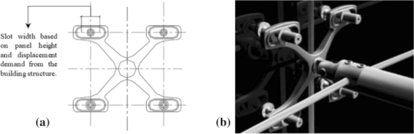
In the last years, several authors carried out experimental and analytical tests to assess the in-plane capacity of PFGFS. In order to improve the capacity of such facade systems for buildings located in high seismic regions, spider elements with horizontally slotted holes have been proposed in literature (Desai et al. 2005; Gowda et al. 2010), as shown in Fig. 5. Using horizontally slotted holes enables for isolated translation of the overall facade, whilst maintaining a vertical load-bearing capacity of the connection. The horizontal holes size should be defined according to the glass facade drift demand from the building structure. For this purpose, drift limits from the Californian Building Code (CBC 2001), in the range of 2 or 2.5% depending on the fundamental period of the structure itself, have been considered in Gowda et al. (2010).
At the Swinburne University of Technology, Melbourne, Australia, two full-scale experimental tests were developed to assess the in-plane capacity of PFGFS (Sivanerupan et al. 2014a, b). The specimens were pushed under quasi-static displacement-control testing regime with displacement increments of 5 mm until reaching the glass failure. These tests were carried out on two facade systems consisting of four 1200 × 1200 mm toughened glass panels, 12 mm thick with 8 mm thick silicone weather sealant joint. During the experimental campaign, two different types of spider elements were adopted: pinned X-Type and fixed K-Type. In addition, numerical models were implemented and benchmarked against the experimental results (Sivanerupan et al. 2014a, b, 2016). In terms of general behavior and mechanisms, as observed from experimental results as well as numerical modelling, PFGFSs tend to accommodate the in-plane movement through three main mechanisms, and the difference between X-Type and K-Type is only related to the first one (Sivanerupan et al. 2014a, b).
The first mechanism, when X-Type elements are used, is related to the in-plane rigid body rotation of the spider element. For K-Type spider element, rigid body vertical translation of the spider element at the base slotted hole connection to the supporting plate is observed. The second mechanism is a rigid body translation, facilitated by the built-in standard gaps between the bolts and hole within the spider arms, as well as between bolts and glass panels. Finally, deformation and yielding of the spider arms is observed. The third and last mechanism allows an out-of-plane movement, facilitated by local bending. The out-of-plane movement coupled with the diagonal tensile stress around the bolted connection, could lead to the brittle failure of the glass panels. For this reason, the third mechanism is critical because it develops a rapid increment of the tensile stresses, possibly and quickly leading to fracture.
In these experimental tests, the maximum allowable drift was 2.01% and 5.25% for X-Type and K-Type spider elements, respectively. This highlights the inherent higher performance of K-Type when compared to X-Type elements. For this reason, as a natural selection for implementation into a whole low-damage building system, this work focuses on K-Type elements, with the aim to increase the understanding on its characteristics and behavior and suggest detailing to further enhance its capacity and expected performance.
4 Finite element modelling of the PFGFS connection systems
This section describes the Finite Element Modelling (FEM) implemented for the connection systems of the spider glazing facades. Various numerical models have been developed in ABAQUS to assess: the behavior of the fixed K-Type connections, the bending of the spider arms, the silicone weather sealant joint and the bolted fixings. Moreover, a macro-modelling of the connection components based on the definition of frame elements, and non-linear links (springs) is also presented.
4.1 The spider element
A 3D FEM model of the connection system (K-type spider element to the supporting plate) is firstly developed in ABAQUS software. As a second step, referring to and building on the obtained micromodel numerical results, a simplified model is proposed by using frame elements and non-linear links, able to describe the frictional behavior between the spider element and the supporting plate.
Specifically, in the first phase two micro-models have been implemented in ABAQUS in order to calibrate:
- the non-linear links to define the spider element-to-supporting plate frictional behavior.2.
- the cross-sectional area of the frame elements used to simplify the overall model. It is fundamental to focus on the spider arms, which have a variable cross-sectional area.
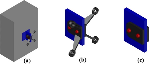
In both cases, it is worth noting an aspect which enables to simplify the ABAQUS models. This allows a reduction of the computational expense, making the model more performing. The spider element is attached to the building structure by a T-shaped stainless steel supporting plate anchored to the beam or column element. The T-shaped support plate is simplified by considering the plate to which the spider element is attached. This element is constrained, by a fixed support, modelling an indefinitely rigid connection to the building structure. Furthermore, to assess only the frictional behavior, the spider arms have been removed from the model. Figure 6a shows the connection of the glazing support attachment to the building structure. Figure 6b, c show the ABAQUS models used to assess the flexural behavior of the spider arms and frictional one of the spider element-to-supporting plate, respectively.
4.1.1 Frictional behaviour of the K-Type spider element
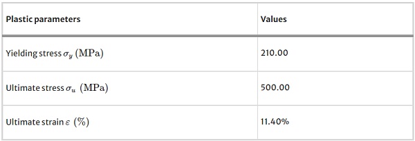
The ABAQUS numerical model developed to assess the supporting plate-to-spider element frictional behavior consists of three parts: the simplified supporting plate, the spider element and the bolts. All the previous parts have been modelled using 3D deformable solid elements made up of hexahedral mesh elements. Specifically, the general-purpose quadratic brick element featured by 20 nodes, with reduced integration (2 × 2 × 2 integration points) is used (C3D20R), Fig. 7a. In this model, two different materials have been adopted. The former is a stainless steel AISI 316, modelled as an elastic material and used for both the supporting plate and spider element. The latter is a stainless steel A4, modelled as an elastic–plastic material and used for the bolts. The parameters used to define the material plasticity depend on the bolt type and its resistance class (CR). Modifying the CR, yielding stress, ultimate stress and ultimate deformation vary. CR 50, 10 mm diameter bolts have been considered in this work. Table 1 summarizes the parameters defining the plasticity of such bolts.
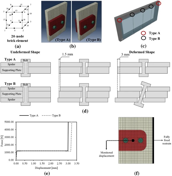
Table 1 Material properties of the CR 50 bolts (10 mm diameter) - Full size table
Frictional interaction has been modelled within contact surfaces. Tangential and normal behaviors have been added to model the frictional interaction. Hard Contact has been considered for the normal behavior, while a friction coefficient has been assumed for the tangential behavior. According to the Italian Building Code (NTC 2018), the friction coefficient μμ for steel-to-steel contact has been assumed equal to 0.30. Thus, this modelling approach has been adopted to simulate the interaction/contact between the supporting plate and spider element as well as between the spider elements and bolt heads. Instead, a different interaction based on Frictionless tangential behavior has been used for the bolt shanks to plates holes contact. Further information about the modelling of the frictional interactions used can be found in the ABAQUS Standard user’s manual (2009).
Finally, a relative movement between the components has been applied to simulate the relative movement between the supporting plate and the spider elements once the critical frictional force is attained. The analyses have been carried out for both the glazing support attachments presented in Fig. 7b. Specifically, two assemblies have been considered, namely Type A and B, respectively. The difference is related to the number of spider elements attached to the supporting plate (i.e., one spider for Type A, and two spiders for Type B). Type A is used when the glazing attachment system supports one glass panel, whereas Type B is used when two glass panels are supported. Figure 7c shows the facade with the location of the alternative assemblies.
Each assembly consists of two 10 mm diameter bolts, supporting plate and spider elements with 13 mm circular holes. This provides a gap of ± 1.5 mm in each direction. For this reason, the closure of the built-in gap oversized hole between bolts and holes within the plates occurs when a relative movement of about 3 mm is applied. It is worth mentioning that only the ideal position of the bolt (i.e., its axis passing through the center of the circular holes within the plates) is assumed. Figure 7d shows the undeformed as well as the deformed configuration of the assembly in order to clarify the maximum allowable displacement related to the built-in standards gaps. The pretension load of bolts should be defined to allow the triggering of the connection sliding for low forces. If the bolt preload is high, the glass breakage could occur even if the connection is designed to accommodate large displacements, as high level of forces can develop causing the glass failure before triggering the sliding mechanism. In the numerical application, the bolt pretension has been defined considering that the spider element can support the self-weight of the glass panel without triggering the sliding, avoiding the vertical settlement of the facade.
Following this approach, the pre-tension force has been calculated as the value strictly necessary to keep the facade in position. Figure 7e presents the force–displacement monotonic curves obtained for both glazing support attachments (Type “A” and “B”). Such curves have been derived through ABAQUS simulations by applying a uniform displacement to the spider elements. Considering the boundary conditions, the supporting plate is fully restrained in correspondence of the surface connecting such element to the structure itself. Finally, a uniform displacement perpendicular to the alignment of bolts, and slightly higher with respect to the maximum allowable gap has been applied. This choice is due to the need to capture the behaviour of the connection when the bolt shank gets in contact with the holes within the plates. Furthermore, Fig. 7f shows the boundary conditions and the point at which the displacement has been monitored.
The first trend of the curve in Fig. 7e describes the frictional behavior of the connection. First the critical force at the frictional interface is achieved, then the sliding is triggered. Thus, sliding continues until the gap closure occurs. In this case, it can be highlighted a sudden stiffness increase causing high stresses that quickly lead to glass failure. The described Finite Element Modelling allows to define the multi-linear (spring) links representing the frictional behavior of such connections. Multi-Linear Elastic elements are used for this scope. It is worth noting that monotonic analyses have been implemented, thus the adoption of these links is acceptable to assess the in-plane capacity of the facade system. If cyclic analyses were needed, different link properties should be used to capture the hysteretic behavior of the facade.
4.1.2 Bending of the spider arms
This section discusses the results obtained by modelling the overall K-type spider element as a 3D model in ABAQUS (Fig. 8a). The numerical model is built following the same approach previously described, plus adding the spider arms. As in the previous case, the C3D20R brick element is used for modelling the spider arms. The study focuses on the evaluation of the component flexural behavior when a vertical force, representing the glass panel self-weight, is applied at the lower spider arm end. The sole lower arm is considered in the simulation as the glass panel is attached to it in its upper part. This choice is related to the need of generating only tensile stresses on the panel when the self-weight acts.
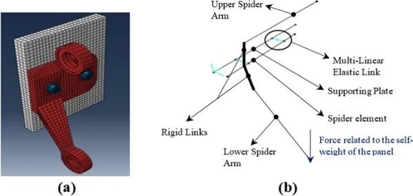
The analysis aims to calibrate the cross-sectional area properties of the equivalent frame system in SAP 2000 (Fig. 8b) to be used in the (lumped plasticity) macro-modelling approach. Frame elements representing the supporting plate and spider components have been modelled using the same cross-sectional area properties of the specific elements. For the spider arms, characterized by variable cross-sectional area properties, several analyses have been performed in SAP 2000 to calibrate the equivalent frame element properties. Specifically, combining the frame elements with rigid links as well as the multi-linear elastic springs previously defined, the simplified macro-model of the assembly can be implemented, and the calibration of the equivalent frame element can be developed. Firstly, from the ABAQUS model it is possible to define the deformed shape of the spider arm when the self-weight of the glass panel acts (dashed line of Fig. 9a).
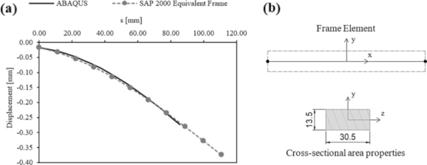
In this case the vertical displacement has been monitored along the curvilinear abscissa “s”. After that, several analyses have been carried out with the simplified macro-model in SAP 2000 varying the cross-sectional properties of the spider arm. In the simplified model, constant cross-sectional properties have been assumed. By mean of an iterative procedure, the cross-sectional properties have been defined benchmarking the results of the macro-model against the curve defined with the complex 3D model implemented in ABAQUS. Figure 9a shows a comparison in terms of vertical displacement shapes obtained for the ABAQUS vs SAP 2000 models. The calibration has been carried out considering the entire model of the glazing support attachment.
This justify that in Fig. 9a the vertical displacement when s = 0 is not nought. This is mainly due to the deformation of the supporting plate when the self-weight of the glass panels acts. Furthermore, it is worth noticing that the model has been calibrated considering the spider arm’s flexural stiffness solely. In fact, even considering the combined tensile and flexural action related to the self-weight of the spider arm, the elongation in the axial direction is deemed negligible when compared with the vertical deflection due to the flexural behavior of the element. A simple frame element with constant rectangular section (30.5 mm width and 13.5 mm height) has been defined to model the complex geometry of the spider arm, Fig. 9b. Considering the simplified model, the spider arm is fully restrained to the rigid link in order to simulate the welded connection of the components to the spider arm plate (Fig. 8b).
Finally, it is worth mentioning that in Fig. 9a the lines representing the deformed shape considering the results from ABAQUS as well as the one from SAP 2000 have different length. The ABAQUS simulation provides the vertical deflection of the spider arm (i.e., from the welded connection to the drilled circular element for the bolted fixing connection, where the self-weight of the glass panel is applied). In the SAP 2000 model, the drilled element is not modelled and a longer frame (i.e., up to the point of application of the vertical force) has been used.
4.2 The silicone weather sealant joint
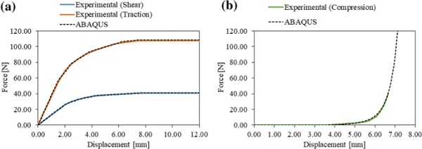
This paragraph focuses on the study of the silicon weather sealant joint behavior. The behavior of such component has been widely investigated through experimental tests on 100 × 100 mm specimens (Sivanerupan et al. 2016). The specimens consisted of two 12 mm thick glass panels, including an 8 mm thick silicone weather sealant joint, and were tested applying tension, compression, and shear forces. This part aims to develop a ABAQUS model for calibrating the silicone material properties, using these experimental tests. The numerical model implemented simulates the features of the specimen tested by Sivanerupan (2016). Different load cases have been defined to replicate the tension, compression and shear tests carried out. Linear and Non-Linear Shell Elements have been used for modelling glass panels and silicone joint, respectively. Silicone has been modelled using an elastic–plastic material for tension and shear forces, whilst for compression forces, a hyper-elastic material has been assumed.
By mean of an iterative procedure, the silicone properties have been defined comparing the results from the numerical model to the experimental results. Figure 10 presents the calibration of the silicone properties, specifically the results from the ABAQUS model benchmarked with the experimental results for traction and shear loads (a), as well as for the compression one (b). Then, parametric analyses have been carried out to evaluate the silicone behavior by modifying the joint thickness (6, 8, 10 and 12 mm). In each case, it can be observed that, when the silicone weather sealant joint thickness increases, the assembly becomes less stiff and can accommodate the in-plane displacement producing less stress on the glass panels (Fig. 11). Figure 11a shows the results for the tension test, Fig. 11b is related to the shear test, whilst Fig. 11c refers to the compression one.
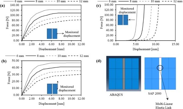
Finally, based on the obtained results, a simplified model in SAP 2000 has been proposed. The glass panel has been modelled using shell elements, whilst a simplified Multi-Linear Elastic link simulating the silicone weather sealant joint has been calibrated referring to the ABAQUS outputs. This approach allows for a less computational expensive and practical analysis, as simplified links replace non-linear shell elements. Figure 11d shows the ABAQUS and SAP 2000 models, respectively. As in the case of the link used for frictional behavior, it is worth noting that more complex links should be used for cyclic analyses. Indeed, Multi-Linear Elastic links are not able to capture the hysteretic behavior of the material they are modelling.
4.3 The bolted fixings
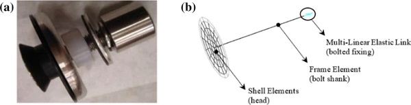
This paragraph aims to assess the behavior of the connection between the glass panels and the spider arm. Figure 12a shows a typical countersunk bolt fixings, while Fig. 12b illustrates how to simplify such component by using 1D frame and link elements and 2D shell elements. The bolt shank has been modelled as a frame element, while a link element has been used to model the frictional behavior of the bolted fixing to the spider arm connection. Finally, shell elements have been used to model the head of the countersunk bolt fixing.
As already mentioned, using an articulated bolted fixing enables to develop a larger in-plane capacity of the facade. This connection consists of a ball joint capable to accommodate further rotation and displacement at the glass to spider connection, without causing excessive stress concentrations. Nevertheless, the lack of experimental tests on such a component makes the implementation of a reliable model a tricky task. For this reason, this paper focuses on fixed systems such as countersunk bolt fixings. Further studies are needed to develop a reliable model for this element and to define simplified links able to capture the behavior of the ball joint. In case a countersunk or button-head bolt fixing is used, the connection between the shank and the head is fixed.
A refined non-linear 3D ABAQUS model has been implemented to assess the frictional behavior of the bolted fixing to spider arm connection. The model is similar to the ones implemented to assess the frictional behavior of the spider element to supporting plate connection and the flexural behavior of the spider arms. Even in this case, the C3D20R hexahedral element has been used for the numerical model in ABAQUS.
In order to evaluate the frictional behavior of the bolted fixing to spider arm, the overall 3D model (Fig. 13a) implemented in ABAQUS has been further simplified. Specifically, only the end part of the spider arm has been used to model the connection. Two types of connections should be analyzed: the connection consisting of a slotted hole (lower) Fig. 13c, and the one consisting of a circular hole (upper) Fig. 13b. Focusing on the slotted and circular connection, Fig. 13b, c show the capability of the system to move horizontally and vertically until the gap closure (oversized hole between bolt and hole within the spider arm).
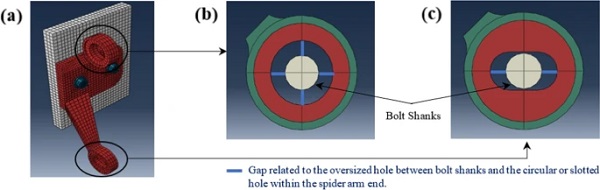
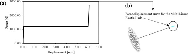
A horizontal displacement has been applied to the model, until the gap closure occurs, in order to evaluate the force–displacement curve of the frictional connection (Fig. 14a) used to calibrate the multi-linear elastic link modelling the frictional behavior into the macromodel (Fig. 14b). In order to model such behavior at the bolted fixing to the spider arm connection into a lumped-plasticity macro-model to assess the overall facade, Multi-Linear Elastic links have been adopted following a similar approach used in the case of frictional behavior between supporting plate and spider components. It is worth noting that a similar analysis should be carried out if a vertical movement is applied. Nevertheless, considering that the vertical gap closure occurs for low displacements (Fig. 13c), using a fixed link in such direction is a good and conservative approximation.
When referring to the spider arm with circular hole (upper part), the same force–displacement of Fig. 14a has been obtained for both the horizontal and vertical directions, since a circular hole enables the same movement in each direction and the gap has the same dimensions of the one in the slotted connection.
5 Numerical model of the overall facade system in SAP 2000
This section discusses the implementation of a simplified model capable to assess the capacity of PFGFSs. Using the results from complex non-linear 3D micro-FEM models developed in ABAQUS, simplified models composed by 1D frames, links and 2D shell elements have been calibrated. This allows to implement a simplified (lumped plasticity) macro-model able to assess the in-plane capacity of the overall facade system. In order to evaluate the interaction between structural and non-structural components, a case-study building has been selected. The macro-model has been developed by referring to a RC frame system with PFGFSs envelope facades.
As already mentioned, the continuous excessive socio-economic losses associated to earthquake events even in well-developed countries have highlighted the need to move towards the development and wide implementation of low-damage systems for both structural and non-structural components (Pampanin 2012, 2015, 2020). Therefore, in this work, an integrated low-damage building is considered as a case-study. Specifically, a low-damage technology has been implemented for the structural skeleton. Considering the non-structural components, PFGFSs are considered as envelope, and both traditional as well as innovative low-damage (proposed in the next sections of this paper) connection systems are used to demonstrate the enhanced resilience of the integrated low-damage building with respect to the case where traditional connection systems for the building envelope are used.
5.1 Description of the case-study building
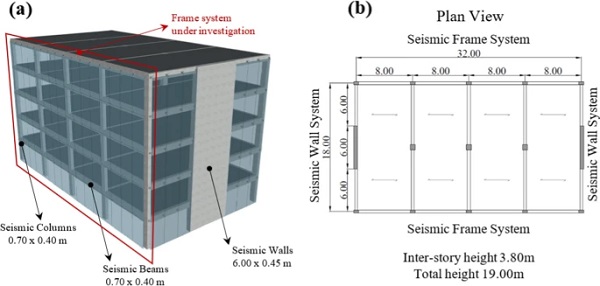
The case-study building is a 5-storeys reinforced concrete building for commercial (office) use (Bianchi et al. 2020). The skeleton consists of two seismic-resistant frames in one direction and two seismic-resistant walls in the orthogonal direction. In the latter direction, the structural system also comprises three gravity frames. The global dimension and plan geometry are presented in Fig. 15. The building is located in a high-seismic prone area (Amatrice, Rieti, Italy).
In order to study the in-plane behavior of the glass facade, the study is developed considering the frame system only. This structural skeleton is designed following the Direct Displacement Based Design (DDBD) philosophy (Priestley et al. 2007; Pampanin 2010) and assuming a design drift of 2%. Typically, frame systems can be designed for a greater drift value than wall systems. This justifies the focus on the frame system, thus allowing for more conservative analyses in terms of facade verification.
The DDBD procedure provides the internal actions on the structural members to be considered for the design of the connections. For this case-study building, a low-damage system for the structural system is used. Indeed, recent earthquakes have further highlighted the need for developing low-damage systems both for structural and non-structural components. For this reason, the case-study building has been designed using the low-damage PRESSS-technology (PREcast Seismic Structural System) rather than a traditional monolithic solution. The PRESSS-technology system has been originally conceived by Stanton et al. (1997), Priestley et al. (1999) and during a research effort carried out during the US PRESSS Program (University of San Diego) in the 1990s. Further extensive developments, leading to code-implementation and practical on-site application has been developed in the past decades in particular at the University of Canterbury in New Zealand (Pampanin 2005, 2010, 2012).
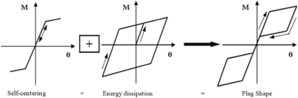
Traditional plastic hinge mechanisms are replaced by a controlled rocking motion at the interface between structural components, i.e., beam-to-column, column-to-foundation and wall-to-foundation connections. The precast elements are jointed together through unbonded post-tensioned bars or cables, which allow for a self-centering of the system following a non-linear elastic rule. Energy dissipation is added by internally located mild steel bars or externally replaceable dissipators, also known as Plug&Play (Sarti et al. 2016). For energy dissipation, the elastic–plastic rule is followed. The combination of self-centering and energy dissipation defines the so-called “Flag-Shape” hysteresis rule (Fig. 16), leading to significantly reduced if not negligible residual deformation. During the earthquake shaking, the connection develops a rocking motion by opening and closing of an existing gap, while the dissipators ensure the system ductility and energy dissipation capability. At the end of the shaking, the unbounded post-tensioned system allows the gap closure with reduced or even negligible residual deformation.
The adoption of such a low-damage technology has been proven to significantly reduce the expected (direct and indirect) losses, including downtime, in the aftermath of an earthquake events (Pampanin 2012; Bianchi et al. 2020).
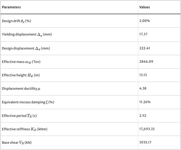
The low-damage connections are designed considering a re-centering ratio λλ equal to 1.50 (60% moment contribution from the unbonded post-tensioned tendons and 40% from dissipative Plug&Play devices). Table 2, summarizes the parameters obtained from the DDBD procedure for the frame structural system considered.
Table 2 DDBD design parameters, frame direction_PRESSS-technology - Full size table
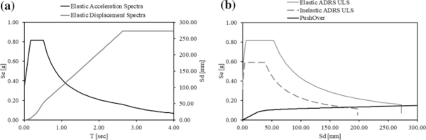
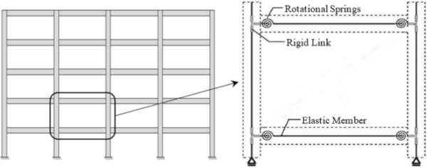
Non-linear static (push-over and push–pull) analyses have been carried out using a numerical lumped-plasticity model developed in Ruaumoko 2D (Carr 2003). The PRESSS frame structure has been modelled using elastic members and two rotational springs in parallel at the beam-to-column and column-to-foundation interfaces (Pampanin et al. 2001). The first rotational spring models the re-centering behavior from the unbonded post-tensioned tendons. This spring is based on a non-linear elastic rule. The second rotational spring models the dissipation from the external replaceable Plug&Play dissipaters. For this second spring, an elastic–plastic rule based on Ramberg–Osgood hysteresis rule is adopted. Figure 17a shows both the acceleration as well as the displacement spectra for the site (Amatrice, Rieti, Italy). Push-over analysis curve has been converted into, and plotted within, an Acceleration-Displacement Response Spectra (ADRS) domain (Fig. 17b). Introducing in the same graph the ULS response spectra, the maximum expected seismic acceleration and displacement for the structure can be evaluated. Specifically, to define the performance point, the Capacity Spectrum Method (CSM) from ATC 40 (1996) has been used considering the equivalent structural viscous damping derived by push–pull analysis.
Then, a reduced portion of the frame-facade system (one storey, one bay) has been considered to study the interaction between structural components and PFGFS. The SAP 2000 lumped-plasticity model, adopted to assess the behavior of such system, is presented in Fig. 18.
5.2 Seismic assessment of PFGFS
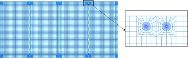
Once the bare frame system has been studied, the numerical model can be completed with non-structural elements. In order to provide a simplified model of the overall facade system, the results from the analysis in ABAQUS are considered. The spider elements and the bolted fixings are modelled by equivalent frame/link systems. The silicone weather sealant joint is modelled using multi-linear elastic links. Finally, the glass panels are modelled using shell elements. Figure 19 shows the model of the overall system used to assess the in-plane capacity of the PFGFS. From this figure, it can be immediately highlighted the refinement of the mesh around the glass panel connection to the bolted fixing.
Non-linear static (pushover) analyses have been performed to compare the behavior of the bare frame system, presented before in Fig. 18, and of the integrated system (bare frame + facade), Fig. 20a. The difference between these two curves allows to assess the in-plane additional capacity (stiffness and strength) contribution provided by the sole facade system Fig. 20b. It is worth noting that the displacement monitored during the non-linear static analysis refers to the upper beam-column joint of the portion of the seismic-resistant frame used to assess the lateral behaviour of the PFGFS.
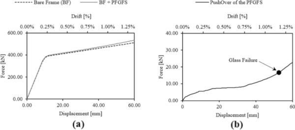
In order to assess the glass failure of the panels, the principal tensile stress has been monitored during the entire analysis. The glass failure is assumed when the glass achieves the maximum tensile stress as defined in the CNR DT-210 (2013). These guidelines provide the maximum allowable tensile stress for the glass panel according to several aspects. Aspect-ratio and dimensions of the glass panels are particularly important in the definition of such capacity. For the facade system herein assessed, consisting of 12 mm thick toughened glass panels 2000 mm width and 3800 mm height, a maximum value of about 82 MPa for the tensile stress is considered.
Moreover, according to the above limits and the analysis of the frame super assembly, the drift value corresponding to the maximum PFGFS capacity is assessed to be 1.17%. This value is significantly lower when compared to 5.25% drift level of the PFGFS with K-Type elements investigated by Sivanerupan et al (2016). This was expected in this analysis; in fact, the in-plane capacity depends on several factors. Sivanerupan et al. (2016) used K-Type elements with vertically slotted holes rather than circular holes, so a greater capacity is expected. In fact, the K-Type elements investigated by Sivanerupan et al. (2016) were able to under-go a relative movement between supporting plate and spider element of about 17.5 mm. This was due to the presence of vertically slotted holes both within the supporting plate and the spider element.
Instead, in the case investigated in this paper, low diameter circular holes have been considered, without vertical slots, so to provide vertical bearing capacity at the connection level. The admitted relative movement was about 3 mm (about 17% of the movement admissible for the previous case). This aspect is one of the reasons for a lower expected drift. In addition, Sivanerupan et al. (2016) carried out several parametric analyses that highlighted the increasing capacity of such systems in case of glass panels with reduced geometrical dimensions. The value of 5.25% was achieved for square panels with a length of 1200 mm. Instead, in the specific case of this paper, rectangular panels of 2000 × 3800 mm are used. Finally, as previously mentioned, in case of larger panels, the maximum allowable tensile stress decreases according to the CNR DT-210 (2013). All these reasons justify a lower capacity of the PFGFS herein assessed when compared to the facade tested at the Swinburne University of Technology.
6 Proposal of an innovative low-damage connection system
With the aim of increasing the in-plane capacity of PFGFSs, an innovative low-damage connection system is herein proposed and analytically-numerically studied. The solution is conceived as a system applicable without the need for an additional aluminum frame, typically adopted in case of reduced facade panels which need more supporting points.
In recent years several solutions have been proposed to improve the ultimate capacity of such components. High-performance systems currently available in the market consist of spider elements including vertically slotted holes. These holes allow the connection to slide until the gap closure, so increasing the dimension of the holes allows to improve the in-plane capacity. Nevertheless, in case of an earthquake, the sliding of the connection causes the bolts yielding. Once the bolt is yielded, loss of preload occurs. Therefore, the bolt is no longer able to counteract the vertical settlement of the facade through the frictional force between the supporting plate and the spider element.
For this reason, even though the glass failure does not occur, vertical settlements of the facade are expected. Thus, this problem highlights that using large slotted holes might not be effective. In fact, even if substantial improvement of the in-plane capacity of the facade is reached, post-earthquake damage to bolts requires local and complex (due to limited accessibility) repairs. Repairs are inevitably leading to direct and indirect costs including business interruption (downtime). In this paper, a new low-damage connection system, able to overcome this problem by introducing horizontally slotted holes, thus maintaining the vertical load (facade self-weight) bearing capacity, is proposed. In this case, the spider and the supporting systems are attached to the structure by rotating themselves 90°. This solution enables the use of horizontally slotted holes. Figure 21a shows the traditional K-Type element, that is the system studied in the previous sections, and the innovative system herein proposed, Fig. 21b.
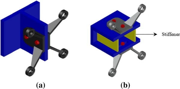
In the previous figure, it can be noticed that the main difference between the two systems is the supporting plate. In the first case, a T-shaped stainless-steel plate is used, while in the latter a C-shaped supporting (stainless-steel) plate with vertical stiffeners is used. The stiffeners are adopted to reduce the excessive deformations that could occur under the load-bearing self-weight of the glass-panel.
As mentioned before, the use of the innovative connection overcomes the vertical settlement problem related to the yielding in the bolts and consequent loss of preload. In the innovative system, even if the bolt preload is lost, bolts can still support the facade with their axial stiffness, while, in traditional systems, if the bolt preload is lost or bolt yields, the connection can no longer guarantee the frictional force that counteracts vertical settlements. Considering the traditional and the innovative connection system, two analyses have been performed with the ABAQUS micro-models. The two analyses have been carried out by applying the same relative displacement between the supporting plate and the spider element until the gap (oversized holes between bolts and holes within the supporting plate and the spider elements) closure. Figure 22 shows the results of such analyses in terms of Von Mises stress distribution. It is worth noting that, as anticipated, in the traditional system model, the bolt deforms in flexure-shear and yields locally, causing the abovementioned settlement and safety issues.
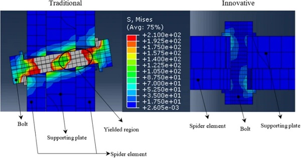
From the results of the analysis on the innovative low-damage connection system, it can be noted that the maximum stress developing in the bolt at the gap closure is about 80 MPa, considerably lower than the yield stress (210 MPa). This aspect confirms that bolts remain elastic (undamaged).
It is worth noting that when modelling the innovative solution, a similar consideration applies to what done for the traditional solution. In this case, the spider element is attached to the building structure by a C-shaped stainless steel supporting system. In order to evaluate the frictional behavior of such a system, there is the need to model the frictional connection of the spider element to the supporting plate only. For this reason, a simplified 3D model is proposed also for the innovative system. The C-shaped supporting plate is simplified by considering the plate to which the spider element is attached. This element is constrained by a fixed support modelling a rigid connection to the building structure. Furthermore, to assess the frictional behavior only, the spider arms have been removed from the model. All the considerations above suggest the possibility to use the same simplified model implemented for traditional connection even for the innovative solution (specifically, for the innovative connection system, the model with only one spider element is considered).
Another crucial difference between traditional and innovative low-damage solutions is the way they accommodate the in-plane movement of the facade. In traditional systems with K-Type spider elements, the in-plane movement is related to the glass panels rocking motion. When the innovative solution is used, the facade is horizontally isolated from the structure itself. Isolated facade systems have already been proposed in the last decades; Brueggeman et al. (2000) highlighted the main advantages of using such systems. Isolated facade enables to significantly reduce the in-plane actions, without increasing the overall system elastic stiffness.
6.1 Parametric study on the innovative low-damage facade system
Parametric analyses have been carried out in ABAQUS for the innovative low-damage facade solution. First of all, multiple analyses have been performed by varying the key parameters such as: a) the dimensions of the horizontally slotted holes in the supporting plate, b) the silicone weather sealant joint thickness, c) the aspect ratio of the facade panel and d) the number of glass panels.
6.1.1 Variation of the hole section
ABAQUS FEM model analyses on the innovative connection have been carried out to define the force–displacement curve of the innovative connection system. In this case, the variation of the dimension of the slotted holes has been investigated. Specifically, the dimension of the hole has been varied from a 13 mm diameter circular hole to an 80 mm horizontally slotted hole, as shown in Fig. 23.
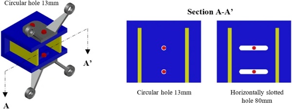
When increasing the dimension/width of the horizontally slotted holes, it can be noticed that gap (oversized holes between bolts and holes within the plates) closure occurs for larger relative displacements, enabling for better in-plane behavior of the facade. Referring to these results, new analyses have been developed in SAP 2000 for the overall innovative facade by varying the spring properties used to model the frictional behavior of the connection system. Figure 24 shows the results obtained from this parametric analysis. Specifically, by increasing the horizontally slotted hole dimension, it can be noted an increase in the maximum allowable drift, which has been measured considering the value causing the failure of the first glass panel of the facade (i.e., when the maximum principle tensile stress reaches the maximum allowable tensile stress as defined by the CNR DT-210). The drift has been measured in this manner for all the other parametric analyses in the following.
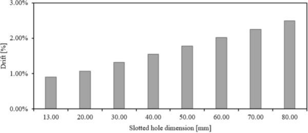
This analysis considers a maximum dimension for the slotted holes equal to 80 mm. A considerable increment in the in-plane capacity can be observed, with the innovative system with an 80 mm horizontally slotted hole reaching 2.49% drift, when compared to the maximum allowable drift of 1.17% in the traditional system.
6.1.2 Variation of the silicone weather sealant joint thickness
In paragraph 4.2, parametric analyses carried out in ABAQUS have highlighted the silicone joint behavior. In particular, the analyses showed that by increasing the joint thickness, the forces transmitted by the silicone to the glass panels are reduced.
Starting from the initial solution with an 8 mm joint thickness, a parametric analysis was carried out increasing the sole joint thickness (to 10 mm and 12 mm). The 6 mm joint thickness is neglected because in this case the in-plane capacity is expected to be lower for the reasons mentioned above. Figure 25 shows the results of the analyses carried out in SAP 2000, considering a facade with an innovative low-damage connection with 80 mm horizontally slotted holes.
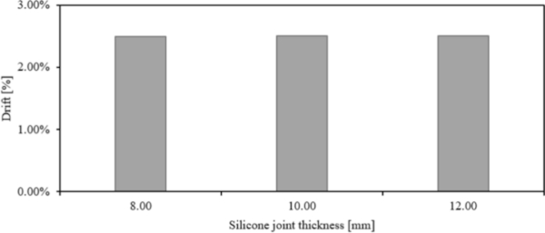
In this case, it can be noticed that the in-plane capacity of the facade, when varying the joint thickness, is roughly constant. When a traditional solution is used, Sivanerupan (2016) showed that increasing the joint thickness can lead to an improved in-plane capacity of the facade. The difference between the two solutions depends on the way the facade accommodates the in-plane movement. In case of traditional facade, the in-plane movement is accommodated by a rocking motion of the glass panels, causing shear stress in the silicone joint. When increasing the joint thickness, the shear forces transferred by the joint to the panels are reduced, allowing for a better in-plane capacity of the facade. In case of innovative solution, the in-plane movement is accommodated by a rigid horizontal translation of the isolated facade. For this reason, the deformation of the silicone joint is almost nihil, thus, the in-plane capacity does not depend on the joint thickness. Figure 26 shows the movement of the facade for the traditional and innovative solutions, respectively.
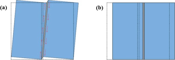
Having a solution not influenced by the joint thickness is essential to overcome tolerances issues as well as assembly errors during construction. The silicone joint has typically a dimension in the order of millimeters, while the glass panels in the order of meters. Therefore, assembly errors influencing the in-plane capacity of traditional PFGFS can be expected.
6.1.3 Variation of the aspect ratio of the glass panels
Experimental tests carried out at the Swinburne University, Sivanerupan (2016), showed that the in-plane capacity of PFGFS is strongly affected by the panel size and aspect ratio. Specifically, panels with reduced size have a better performance. In these experimental tests, square panels with 1200 mm width were used. The connection system consisted of K-Type spider element with vertically slotted holes. In this case, the maximum allowable drift was about 5.25%.
The analyses carried out in SAP 2000 have shown a maximum allowable drift of 2.49% for rectangular 2000 × 3800 mm glass panels, with a connection system consisting of an innovative low-damage connection with 80 mm horizontally slotted holes and 8 mm thick silicone weather sealant joint. Therefore, a parametric analysis has been herein carried out to define the increment of the in-plane capacity of the facade when reduced panel dimensions are used. In particular, the panel width has been reduced, maintaining a constant height of 3800 mm equal to the inter-story height. This choice is related to the need for supporting the facade only in correspondence of the structural elements, thus without using an aluminum frame to connect the facade at intermediate points. Figure 27a shows a schematic representation of the façade system varying the glass panels width, whilst Fig. 27b shows the in-plane capacity of the facade comprising four (2000 mm width), six (1300 mm width) and eight (1000 mm width) panels, respectively.
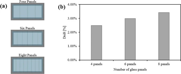
Considering the most performing solution herein proposed, consisting of low-damage connections with 80 mm horizontally slotted holes, 8 mm thick silicone sealant weather joint and eight 1000 × 3800 mm panels, the maximum allowable drift is 3.42%. Again, this value is lower than the maximum drift level achieved in Sivanerupan’s experimental tests carried out at the Swinburne University (5.25%). This can be justified as related to the glass panels size and aspect-ratio. The experimental tests demonstrated that reducing the dimensions of the glass panels, larger in-plane capacity can be achieved. The glass panels herein used have a rectangular shape and dimensions notably larger than those used in the tests. In addition, the maximum allowable tensile stress is strongly related to the aspect-ratio and dimensions of the glass panels (CNR DT-210 2013).
All these aspects justify a lower in-plane capacity of the systems herein proposed when compared to tests carried out at the Swinburne University. Using panels with reduced height and introducing an aluminum frame, as in the case of the experimental tests, the in-plane capacity of the proposed solutions is expected to further increase. Besides, further drift increment can be achieved increasing the horizontal slotted holes with respect to the maximum value assumed for the parametric analysis presented before. Finally, even if the facade herein proposed has a lower in-plane capacity, there is the crucial advantage, mentioned above, to have a more performant behavior of bolts which remain elastic. This reduces the damage due to yielding and preload loss of the traditional solution, as mentioned previously, thus guaranteeing a more effective and safer load-bearing (self-weight) capacity of the facade system.
7 Further investigations through non-linear time history analyses
In this section, the seismic behavior of the overall building system (previous case-study) is investigated through Non-Linear Time History Analyses (NLTHAs), focusing on the behavior of PFGFS. The analyses focused on frame structural systems. 2D models have been implemented in Ruaumoko2D (Carr 2003). Two different earthquakes intensity levels have been selected: Design Basis Earthquake (DBE) ground shaking (the Ultimate Limit State level), with a probability of exceedance of 10% in 50 years; and the Maximum Credible Earthquake (MCE) ground shaking, corresponding to a probability of exceedance of 2% in 50 years. Two suites of seven recorded natural accelerograms have been derived by the online software RexeLite (2011).
Considering the design response spectra for both intensity levels, records have been properly scaled considering a range in the neighborhood of the fundamental period T1. The spectrum-compatible natural accelerograms have been selected following the indication of the Italian Building Code (NTC 2018, Sect. 3.2.3.6). Table 3 summarizes the characteristics of the selected records for both the DBE and MCE. Figure 28 presents the two suites of records, and the average spectrum of the records compared with the design spectra based on the Italian Building Code (NTC 2018) for the two intensity levels.
Table 3 List of selected earthquakes records - Full size table
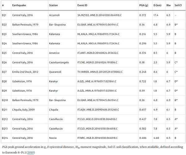
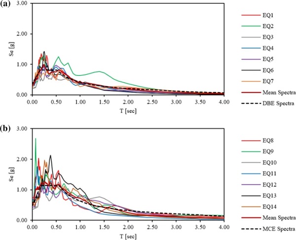
Figure 29 presents the maximum inter-story drift obtained for each earthquake record. Mean values both for DBE and MCE are shown (thick black lines).
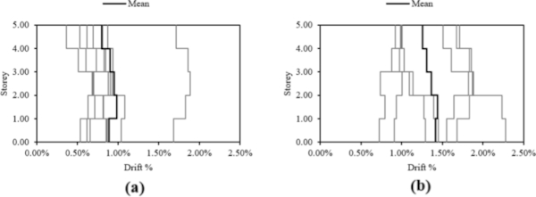
It is worth noting that the Non-Linear Time History Analyses herein proposed have been performed on the bare-frame system. This approximation is in general justified when limited interaction between structural and non-structural components are expected. In this case, it has in fact been noted, as discussed previously and reported in Fig. 20a, that the PFGFS facade system does not affect the initial stiffness and strength of the structure itself.
Considering the 2% design drift assumed in the DDBD design and building on the parametric study proposed in this paper, an adequate low-damage facade system has been specifically designed. Specifically, the attachment system is composed by an innovative low-damage connection system with 60 mm slotted holes. The PFGFS consists of four 12 mm thick toughened glass (2000 × 3800 mm) panels with 8 mm thick silicone weather sealant joint. Figure 30 presents the mean demand drift by DBE and MCE, respectively (solid grey and black lines) as well as the maximum allowable drift (2.02%) limit states for the selected PFGFS (dashed line). The analyses carried out have shown that no failure occurs at either DBE or MCE levels. In addition, using the innovative connection system, bolts remain elastic. For this reason, even under severe earthquakes, the facade system is expected to show negligible damage.
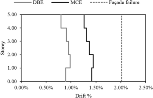
Also, considering the experimental tests carried out at the Swinburne University of (Sivanerupan et al. 2014a, b), it can be assumed that no silicone joint damage occurs for both DBE and MCE. Silicone joint damage is achieved for drift levels of about 2%, and thus the facade systems is expected to continue to be an effective shield for water, air and moisture from outdoor, also after both intensity levels.
8 Conclusions
The paper has discussed and investigated the seismic behavior of point fixed glass facade systems (PFGFS), focusing on both refined 3D non-linear FEM and simplified lumped plasticity macro-modelling. Although PFGFS are in general more performing than traditional glazed facade systems, these envelope systems have shown vulnerability in past earthquakes. Nevertheless, high-performance attachment systems, consisting of vertically slotted holes, which allow to improve the in-plane capacity, are currently available in the market. Even though high in-plane capacity can be achieved using such systems, local damage to the connection leading to economic losses, possibly compromising the (self-weight) load-bearing capacity, is expected. Therefore, a new low-damage connection system has been herein proposed and compared with the traditional solution.
As a first task of the present work, refined non-linear 3D FEM implemented in ABAQUS have been used to assess the behavior of PFGFS at a local level (connection level), as well as the behavior of the silicone weather sealant joint. Based on these analyses, simplified (lumped plasticity) macro-models comprising frame and link elements have been implemented to reproduce the complex mechanisms assessed through the refined FEM models in ABAQUS. Using the simplified macro-model approach, the overall in-plane capacity of traditional PFGFS has been assessed.
After an earthquake, traditional attachment system shows yielding and preload losses in bolts. This aspect compromises the ability of the attachment system to counteract vertical settlements of the facade through the frictional mechanism at the connection level. Therefore, an innovative low-damage system able to accommodate in-plane displacement of the facade without causing excessive stress in bolts has been presented, numerically investigated and discussed. The innovative system is based on horizontally slotted holes rather than vertically slotted ones. Refined 3D models have been implemented also for the innovative solution, and a new macro-model has been proposed to assess the capacity of the facade equipped with such an attachment system. Moreover, a parametric study upon the innovative system has been carried out. Parametric analyses have been implemented in order to define which parameters mostly influence the in-plane capacity of the system. Specifically, the dimension of the slotted holes and the glass panels size strongly affect the performance of PFGFS even if equipped with the novel attachment system.
Finally, Non-Linear Time History Analyses have been carried out on a case-study building. Results from such analyses, implemented both for DBE and MCE intensity level, have been used to verify the selection of the facade system. Specifically, knowing the maximum inter-story drift assumed in the DDBD and based on the parametric study mentioned above, an adequate low-damage facade system has been specifically designed. Non-Linear Time History Analyses have shown that negligible damage of the facade is expected for both DBE and MCE.
Further investigations on PFGFS can focus on the interaction between out-of-plane demand and in-plane capacity of such a system. In addition, articulated bolted fixings (spherical joint) are currently available in the market. This system can accommodate further in-plane displacement without causing excessive stress concentration. Therefore, using articulated bolted fixings can further increase the performance of PFGFS. The effect of spherical joint should be accurately considered using non-linear links. Nevertheless, experimental tests on such a component would be useful to calibrate refined 3D FEM and simplified links.
Data availability
The dataset generated during and/or analysed during the current study are available from the corresponding author on reasonable request.
References
Acknowledgements
The first author acknowledges the financial support of the Italian Ministry of University and Research (MUR) through the Doctoral Scholarship. The second author acknowledges for the funding from the European Union’s Horizon 2020 research and innovation programme under the Marie Skłodowska-Curie Grant Agreement No. 101029605 (H2020-MSCA-IF-2020—SAFE-FACE—Seismic SAFety and Energy efficiency: Integrated technologies and multi-criteria performance-based design for building FACadEs).
Funding
Open access funding provided by Università degli Studi di Roma La Sapienza within the CRUI-CARE Agreement. Open Access funding provided by the Transformative Agreement among Sapienza University of Rome and Springer Nature Journals.
Author information
Authors and Affiliations
Department of Structural and Geotechnical Engineering, Sapienza University of Rome, Rome, Italy - Simone D’Amore & Stefano Pampanin
Department Architectural Engineering + Technology, Technische Universiteit Delft, Delft, The Netherlands - Simona Bianchi
ARUP, Amsterdam, The Netherlands - Jonathan Ciurlanti
Contributions
Simone D’Amore: conceptualization, investigation, formal analysis, data curation, writing-original draft; Simona Bianchi and Jonathan Ciurlanti: conceptualization, writing-review and editing; Stefano Pampanin: conceptualization, supervision, writing-review and editing.
Corresponding author
Correspondence to Simone D’Amore.


.")