Authors: Socrates C. Angelides, James P. Talbot & Mauro Overend
Source: Glass Structures & Engineering volume 4, pages 403–420 (2019)
DOI: https://doi.org/10.1007/s40940-019-00107-4
Abstract
Laminated glass panels are increasingly used to improve the blast resilience of glazed facades, as part of efforts to mitigate the threat posed to buildings and their occupants by terrorist attacks. The blast response of these ductile panels is still only partially understood, with an evident knowledge gap between fundamental behaviour at the material level and observations from full-scale blast tests. To enhance our understanding, and help bridge this gap, this paper adopts a ‘first principles’ approach to investigate the effects of high strain-rate, associated with blast loading, and the in-plane restraint offered by blast-resistant frames. These are studied by developing simplified analytical beam models, for all stages of deformation, that account for the enhanced properties of both the glass and the interlayer at high strain-rates.
The increased shear modulus of the interlayer results in a composite bending response of the un-fractured laminated glass. This also enhances the residual post-fracture bending moment capacity, arising from the combined action of the glass fragments in compression and the interlayer in tension, which is considered negligible under low strain-rates. The post-fracture resistance is significantly improved by the introduction of in-plane restraint, due to the membrane action associated with panel stretching under large deflections. This is demonstrated by developing a yield condition that accounts for the relative contributions of bending and membrane action, and applying the upper bound theorem of plasticity, assuming a tearing failure of the interlayer. Future work aims to complete the theoretical framework by including the assessment of plate-action and inertia effects.
Introduction
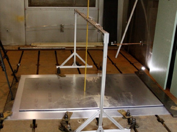
Renewed focus on the threat posed to buildings and their occupants by terrorist attacks has intensified the demand for blast resilient buildings. A high percentage of injuries in blast events are glass-related. As a result, it is now recommended for the glazed facades of commercial and residential buildings under blast threat to include laminated glass panels. These usually consist of two layers of annealed glass with a polyvinyl butyral (PVB) polymer interlayer that fails in a more ductile manner than glass alone, and holds the glass fragments together after fracture, thereby reducing glass-related injuries in blast events. The response of such panels to blast loads is a complex, multi-disciplinary topic that often requires the use of full-scale blast testing to validate designs. It has become common practice for such tests to characterise the panel structural response by the (centre of panel) peak-displacement.
Much research has therefore focussed on reproducing the experimentally recorded, peak-displacement time-histories of laminated glass panels, whether this is by finite-element analysis (FEA) (Hooper 2011; Larcher et al. 2012; Hidallana-Gamage 2015; Zhang and Hao 2015; Pelfrene et al. 2016), analytical solutions (Yuan et al. 2017; Del Linz et al. 2018) or equivalent single-degree-of-freedom (ESDOF) methods (Special Services Group, Explosion Protection 1997; Applied Research Associates 2010; Morison 2007; Smith and Cormie 2009). This approach, of developing models based on experimentally observed, peak displacements, enables the structural assessment of laminated glass panels under blast loading without having to perform additional, expensive blast testing.
However, the fundamental, underlying physics of the panel response is often not explicitly expressed in these models, particularly those describing the post-fracture response, which prevents practicing engineers from understanding fully the contribution of individual parameters and limits their ability to optimise designs. In addition, inconsistent assumptions between existing models, signify that a number of aspects of the structural response remain only partially understood and the need for an improved theoretical framework to be developed.
This paper adopts a ‘first principles’ approach that aims to enhance our understanding of the blast response of laminated glass panels, by bridging the knowledge gap between the fundamental behaviour at the material level and the response observed in full-scale blast tests. Our starting point is the static response of simply-supported, axially unrestrained, laminated glass with a PVB interlayer, loaded laterally (i.e. bending about the minor axis). Such specimens form the basis of much of the experimental work on laminated glazing, as typified by the work of Kott and Vogel (2003, 2004, 2007).
This work reported on four-point bending tests aimed at investigating the pre- and post-fracture bending capacity of laminated glass. It was concluded that, in the pre-fracture stage, the degree of composite action depends on the shear-stiffness of the interlayer, with the response described either by simple bending theory, with the glass layers bending independently out-of-plane (also known as the ‘layered limit’), or by the sandwich theory of thick faces (also known as the ‘composite response’). This stage terminates once the fracture strength in either of the glass layers is exceeded, after which the entire load is carried in bending by the un-fractured layer. In the third and final stage, both glass layers have fractured and can no longer resist tension.
Any residual bending resistance is provided by the composite action of the interlayer, working in tension, and the compression of the glass fragments that come into contact as the panel deforms. However, it was demonstrated from the above experiments that this residual bending capacity was negligible, as the samples collapsed when both glass layers had fractured. This was also the conclusion of the analytical modelling presented by Galuppi and Royer-Carfagni (2018), who calculated a value of 10−310−3 for the ratio of the pre- to post-fracture bending stiffness under low strain-rates.
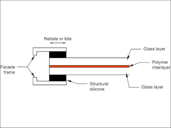
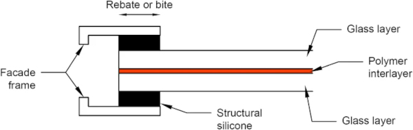
Whilst providing valuable insight into the behaviour of laminated glass, the conditions of these static, laboratory tests differ from those in real-world buildings. Firstly, in building facades, rectangular panels of laminated glass are often supported along all four edges, resulting in a two-way spanning action that influences the deformation of the panel. Additionally, a common requirement for the frames of laminated glass panels is the provision of some form of in-plane restraint, to enhance their overall blast resistance. The Centre for the Protection of National Infrastructure (CPNI) recommends, as a minimum, the application of either structural silicone sealant (wet glazing) or polysulphide sealant, within a rebate of 30 mm, as illustrated in Fig. 1 (CPNI EBP 2014).
Alternatively, elastomeric gasket strips (dry glazing) within 35 mm rebates are also considered acceptable. In the American standards, ASTM F2248-12 (F2248 2012) and PDC-TR 10-02 (PDC-TR 2012), the use of adhesive glazing tape for providing in-plane restraint is also permitted. This difference in boundary conditions governs the level of membrane action within a panel, and is expected to influence significantly the overall blast resistance. Finally, in general, any static testing fails to account for the dynamic nature of the blast response, in particular, the effects of inertia and high strain-rate. The effects of inertia are known to be significant under the accelerations experienced by a panel during a typical blast event, but they will not be considered further here. Instead, we focus on the effect of strain rate on the panel response, which is believed to be important given the viscoelastic nature of the interlayer.
This paper begins by reviewing previous experimental work that has assessed and quantified the effect of the high strain-rates associated with blast loading on the material properties of laminated glass. The outcome of this review forms the basis of the subsequently presented analytical models that aim to describe the enhanced bending capacity of laminated glass under high strain-rates. The influence of in-plane restraint on the quasi-static response under high strain-rates is then evaluated. This quasi-static approach represents a hypothetical load case that simulates blast loading but uncouples the material and inertial effects within the response, thereby focusing solely on the former and enabling the relative contribution of bending and membrane action developed under large deflections to be assessed.
Understanding the effects of high strain-rate and in-plane restraint with these simplified models is the primary objective of the work. This is expected to enhance the theoretical framework available to practicing engineers, thereby ultimately assisting them in optimising the blast design of laminated glass panels, whether by FEA, ESDOF methods or analytical solutions. This work is also considered to be a starting point for future research on bridging the knowledge gap between the material response under quasi-static loading and full-scale blast testing, which will focus on the effects of inertia and two-way spanning plate-action.
The influence of strain rate on material properties
The pressure time-histories resulting from the detonation of high-explosives are of short duration, typically of the order of milliseconds. These result in high strain-rates in any façade panels exposed to the blast. Mean strain-rates ranging from 7.6 to 17.5 s⁻¹ were recorded in fractured laminated glass panels by Morison (2007), and from 10 to 30 s⁻¹ by Hooper (2011), both during open field, high-explosive blast tests. The influence of these strain rates on the salient material properties governing the structural response of the glass and PVB are discussed below.
Glass layers
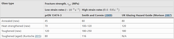
Of fundamental concern is the tensile strength of glass panels, in the presence of surface flaws developed during manufacturing, installation and service-life. The fracture stress (i.e. the stress at which cracking begins) is therefore not a material constant and often requires testing to determine its exact value, which depends on the surface quality and size of panel, and the stress history, residual stress and environmental conditions (Haldimann et al. 2008). The draft European Standard, prEN 13474-3 (2009), recommends a characteristic value for the design fracture strength of annealed glass of 45 MPa, based on a 5% characteristic value that was obtained from 741 static tests performed on 6 mm thick, annealed glass panels.
High strain-rates result in an enhanced fracture strength, as flaws require time to develop into cracks (Overend and Zammit 2012; Larcher et al. 2012). This is observed in multiple, high strain-rate experimental tests performed by Nie et al. (2009, 2010), Peroni et al. (2011), Zhang et al. (2012) and Meyland et al. (2018). For the blast design of glazing, recommended dynamic fracture strength values are presented by Smith and Cormie (2009) that were derived by extrapolating to the high strain-rates associated with blast loading the inherent, static strength value of annealed glass presented in prEN 13474-3using Brown’s integral (risk integral) for stress fatigue (also known as sub-critical crack growth), and superimposing the relevant surface pre-stress from the thermal processing of heat-strengthened and toughened glazing products. Lower strain-rates were considered in the above extrapolation for monolithic glazing, compared to the mean values recorded experimentally by Morison (2007) and Hooper (2011) for fractured laminated glass, as strain-rates depend on the maximum deflection of the panel.
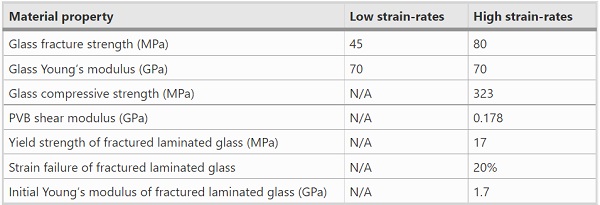
As the pre-fracture stage of laminated glass is limited to smaller deflections, compared to the overall response, the fracture strength derived for monolithic glazing is also considered appropriate for laminated glass. Table 1 shows that these values are in good agreement with the recommendations of the UK Glazing Hazard Guide, which were established from a significant number of independent blast tests (Morison 2007). However, comparisons with more recent, full-scale blast tests on laminated glass panels by Del Linz et al. (2018) have suggested that a fracture strength of 100 MPa for annealed glass is more realistic.
Furthermore, it should be noted that the dynamic fracture strength is also dependent on the boundary conditions and geometry of the panel, as demonstrated by blast tests performed by Osnes et al. (2018) on monolithic annealed glass. As a final comment, the recommended design fracture strength values shown in Table 1 refer to new (as-received) glass. In reality, flaws accumulate in the glass surface over its service-life, and this has been shown to significantly reduce the fracture strength (Datsiou and Overend 2017a, b). This reduction in strength of aged glass was also demonstrated in the high strain-rate experiments by Kuntsche (2015) and Meyland et al. (2018), but this is not considered further here.
Table 1 Recommended design values for glass fracture strength of low (prEN 13474-3) and high (Smith and Cormie 2009; Morison 2007) strain-rates - Full size table
Compressive and tensile tests under high strain-rates performed by Zhang et al. (2012) concluded that the Young’s modulus of annealed glass is insensitive to strain-rate. Therefore, in this paper, the value of Young’s modulus (Eg=70GPa) recommended by prEN 13474-3 (2009) for low strain-rates will be also assumed for blast loading.
Following the fracture of the glass layers in a laminated panel, the attached glass fragments can still provide resistance by generating compressive contact stresses, as discussed in Sect. 3. The effects of high strain-rate on the compressive strength of glass must therefore also be investigated. The theoretical, compressive strength of glass is significantly higher than the fracture strength, as surface flaws will not grow and propagate under compression. Dynamic increment factors (DIF) were derived by Zhang et al. (2012) from dynamic compression tests using a Split Hopkinson Pressure Bar, to amplify the low strain-rate, nominal compressive strength of annealed glass (σg,c=248MPa) for use under high strain-rates:
![]()
For a typical strain-rate of 10 s⁻¹, representative of blast response, Eq. 1 yields a dynamic, compressive strength for annealed glass of σg,c=323 MPa. In practice, however, the Poisson’s ratio effect and any buckling will generate tensile stresses under compressive loading, thereby resulting in a nominal compressive strength lower than the theoretical value (Haldimann et al. 2008). The application of the compression strength of glass, experimentally derived with Split Hokinson Pressure Bar tests, to the post-fracture response of laminated glass therefore requires further experimental validation.
Interlayer
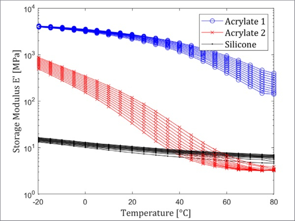
The most popular interlayer for laminated glass panels is polyvinyl butyral (PVB), which is a ductile viscoelastic polymer that is temperature and strain-rate dependent. The main reasons that often make it the preferred interlayer are its ability to block UV radiation, its high strain at failure and its good adhesion properties, which enable it to retain glass fragments following the fracture of the glass layers (Haldimann et al. 2008). In contrast to the low strain-rate, hyperelastic material behaviour observed in uni-axial tension tests of PVB alone, for the higher strain-rates associated with blast loading the behaviour resembles an elastic–plastic response with strain hardening (Kott and Vogel 2003; Bennison et al. 2005; Iwasaki et al. 2007; Morison 2007; Hooper et al. 2012a; Kuntsche and Schneider 2014; Zhang et al. 2015; Chen et al. 2017). It is noted that the above behaviour can vary for different PVB types and depending on the manufacturer. Additionally, temperature dictates the strain-rate at which the observed behaviour transitions from hyperplastic to elastic–plastic. However, the focus of this paper is on the effects of strain-rate at constant, room temperature. Although thermo-rheological effects cause the temperature of the interlayer to increase at high strain-rates, this is not explicitly accounted for here. Rather than adopting a viscoelastic material model, a simpler elastic–plastic model is assumed for the pre-fracture blast assessment of laminated glass.
It is worth noting that Morison (2007) highlighted that the sudden stiffness reduction observed following the apparent yielding of PVB is in fact non-linear viscoelasticity, as permanent strain is not observed following the removal of the load. The description of an elastic–plastic behaviour of PVB at high strain-rates therefore refers to the bilinear shape of the stress–strain response and not to true plasticity. However, this paper considers only the loading phase of the PVB (corresponding to the positive phase of blast loading) for which a simple linear-elastic model is acceptable. During the pre-fracture stage of a panel response, the interlayer is not expected to yield due to the dominant stiffness of the glass layers.
This assumption is supported by the findings of Dharani and Wei (2004), Wei and Dharani (2005) and Hooper et al. (2012b), both of whom presented a finite-element sensitivity analysis of the blast response of laminated glass panels and concluded that the viscoelastic shear relaxation modulus may be replaced by the instantaneous shear modulus (Gpvb=0.178(Gpvb=0.178 GPa). This value is adopted for the pre-fracture analytical models presented in Sect. 3.1. Assuming a Poisson’s ratio of νpvb=0.49 for the essentially incompressible PVB, the corresponding Young’s modulus (Epvb=0.53 GPa) can then be obtained (Morison 2007), although the final response is insensitive to the particular value due to the dominance of the glass layer stiffness pre-fracture.
Table 2 Material properties for cracked, laminated glass with 10 mm fragment length and 1.52 mm interlayer, derived experimentally for low and high strain-rates by Hooper (2011) - Full size table
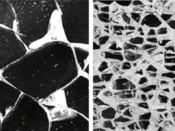
Following the fracture of the glass layers, the response of the PVB interlayer is influenced by the presence of the attached glass fragments. A new constitutive law is therefore required to describe the composite action of the interlayer together with the attached glass fragments. The glass fragments effectively prevent the PVB from extending where it remains bonded to the glass. Therefore, instead of having a uniform extension over the entire area of the PVB, the extension is discretised at the bridges between the fragments, causing significantly larger but localised strains. Thus, under blast loading, stiffening effects are mobilised by both high strain-rates and the attached glass fragments. This has been reported by Morison (2007), Hooper (2011) and Zobec et al. (2014).
Hooper (2011) performed a series of uni-axial tension tests on fractured, laminated glass specimens for a range of strain-rates. An elastic–perfectly-plastic stress–strain response was observed in these tests, governed by the delamination of the attached glass fragments from the interlayer that differs from the elastic–plastic with strain hardening (bilinear) material law observed for the PVB alone. Additionally, a brittle failure was observed in these tests for thinner PVB interlayers, while for interlayers thicker than 1.52 mm, the delamination front travelled quickly, relieving the interlayer from excessive strains and preventing premature tearing.
This conclusion is in agreement with the UK Glazing Hazard Guide recommendation for a minimum PVB thickness of 1.52 mm for blast-resistant laminated glass (Morison 2007). A brittle failure, however, may also occur for thicker interlayers, if a high adhesion grade is specified for the panel that prevents the attached glass fragments to locally delaminate from the interlayer, as observed in the full-scale blast tests presented by Pelfrene et al. (2016). It is clear that the attached glass fragments influence both the elastic and plastic response of the PVB within a fractured panel.
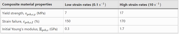
For the purposes of the post-fracture analysis presented in Sect. 3, the PVB may be characterised by Hooper’s (2011) high strain-rate values of the three material properties summarised in Table 2, that is, the yield strength, initial Young’s modulus and failure strain. These values were derived experimentally by Hooper (2011) for specimens with uniform cracking pattern consisting of 10 mm fragments, which aimed to simulate the failure observed from full-scale blast tests of laminated glass panels with annealed glass layers, and for a 1.52 mm thick interlayer, typical of façade glazing panels. However, it is recommended by Hooper (2011) that a strain limit of 20% is applied to the blast design of laminated glass to prevent complete debonding of the attached glass fragments. Although it is acknowledged that there is degree of uncertainty, this limit is also adopted here, with further experimental work required to validate this design limit. To gauge the influence of cracking patterns, Hooper (2011) also derived material properties for both 20 mm fragments and non-uniform cracking patterns. It should also be noted that these values can vary for different PVB types (stiffness and adhesion level) and ambient temperatures.
For comparison, Table 2 summarises material property values recorded under two different strain-rate values during uni-axial tension tests performed by Hooper (2011). The effect of strain rate on the material properties is clear. The consequences for the structural response are now investigated in Sect. 3.
Analytical models accounting for high strain-rates and in-plane restraint
The effects of high strain-rate and in-plane restraint on the blast response of laminated glass panels are often obscured in current models. To assess the influence of high strain-rate on the structural response, this section presents simplified analytical models to calculate the enhanced moment capacity of laminated glass, by adopting the values established in Sect. 2 for the salient material properties. These simple bending models, corresponding to unrestrained, simply-supported beams under uniformly distributed loading, can then be compared directly with the existing low strain-rate experimental results described in Sect. 1. The enhanced resistance provided by the introduction of lateral restraints, as described in Sect. 1, is then evaluated through the consideration of a quasi-static loading under high strain-rates that enables an investigation of the material effects alone, leaving inertial effects to be considered later. Important conclusions can be drawn from a better understanding of the quasi-static response, including the relative contribution of bending moments and membrane forces to the overall bending resistance.
Simple bending analysis
The static response of sandwich beams with low, core shear stiffness is governed by both bending and shear deflections. When the core shear stiffness is negligible, the faces of a sandwich beam bend independently as two separate beams, known as the ‘layered limit’. Additionally, in the case of thick faces, local bending of the faces about their own centroidal axes also influences the shear deformation of the core (Allen 1969). The pre-fracture phase of laminated glass under static loading falls within this category, with available analytical solutions for various loading and boundary conditions presented by Galuppi and Royer-Carfagni (2012). If on the other hand, the shear stiffness of the core is sufficiently high that the plane sections remain plane the response of the sandwich beam is in pure bending of the whole cross-section, known as the ‘monolithic limit’.
The above described ‘monolithic’ behaviour is considered to describe the blast response of laminated glass, due to the enhanced shear modulus of PVB under the high strain-rate, as described in Sect. 2.2, which is now capable of transferring the horizontal shear forces (Norville et al. 1998; Kuntsche and Schneider 2013). Thus, in the unfractured phase (Stage 1), when both glass layers remain unfractured, the laminated glass acts compositely as a single beam. The same approach is adopted by the blast analyses cited in Sect. 1, and the validity of this will be confirmed in Sect. 4.1.
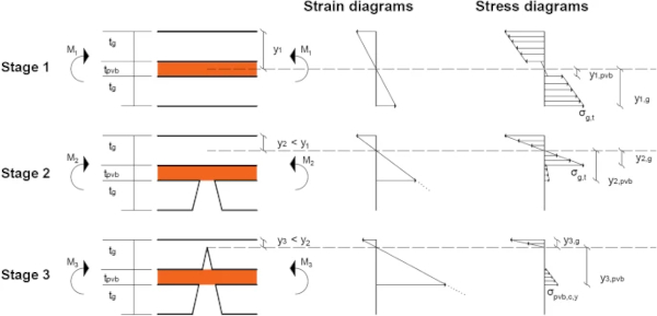
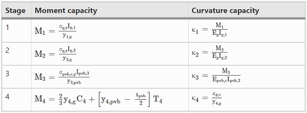
In this section, analytical models for simply-supported, axially unrestrained laminated glass under high strain-rate are presented, assuming a simple bending response and the same elastic stages of deformation (Stages 1, 2 and 3) defined by Kott and Vogel (2003, 2004, 2007) and described in Sect. 1. Based on the Euler-Bernoulli theory, that plane sections remain plane during bending, with small displacements/rotations assumed, an equivalent, transformed cross-section made entirely from either glass (Ig,1,Ig,2 and Ig,3) or PVB (Ipvb,1,Ipvb,2 and Ipvb,3) will be considered for the analysis, based on the modular ratio of the two materials (Eg/Epvb or Eg/Epvb,c). Both transformed sections should result in the same bending stiffness (EgIg=EpvbIpvb or EgIg=Epvb,cIpvb). The positions of the elastic neutral axes from the top of the cross-section in the three stages (y1,y2 and y3), which define zero bending strain, can be then obtained from the first moment of area of the transformed cross-section. The bending strain and stress distributions for each stage are shown in Fig. 2, and the corresponding bending moment and curvature capacities are provided in Table 3.
The bending moment capacity of Stage 1 (M₁) is defined as the moment required for the tensile fracture strength of glass under high strain-rates (σg,t) to be exceeded. Due to the sagging response of the composite structure under a transverse loading (as drawn in Fig. 2), the bottom glass layer will be in tension and therefore fracture first. The bottom glass layer will then no longer contribute to the bending capacity, the bending stresses will be distributed only in the top glass layer and the interlayer, and the response will be governed by the new transformed section (Ig,₂).
The bending moment capacity of Stage 2 (M₂<M₁) that is defined as the moment required for the tensile fracture strength of glass under high strain-rates (σg,t) to be exceeded in the top glass layer, will be smaller compared to Stage 1, due to the reduced second moment of area (Ig,₂<Ig,₁). This will result in an abrupt transition between Stage 1 and 2 in the moment–curvature relationship, as the bending moment that caused fracture in Stage 1 cannot be sustained in Stage 2 under static loading. For short duration pulses, such as blast loads, the response is different due to the inertia effects. As this is beyond the scope of this paper, each Stage will be assessed independently for its moment capacity. Future experimental tests will be used to simulate these stages and validate the derived capacities.
Table 3 Bending moment and curvature capacities of laminated glass for each stage under high strain-rates - Full size table
In Stage 3, both glass layers have fractured but the interlayer still behaves elastically (σpvb<σpvb,c,y). The bending resistance is therefore provided by the composite action of the interlayer in tension and the attached glass fragments in the top glass layer generating compressive contact stresses at glass fragment interfaces (Ipvb,₃). The post-fracture, elastic moment capacity (M₃) is defined as the bending moment required to cause yielding (σpvb,c,y) in the extreme fibre of the interlayer (ypvb,₃).
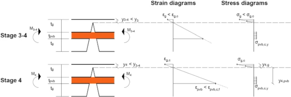
Once the extreme fibre of the interlayer has yielded, the plastic response will initiate. By using the elastic–perfectly-plastic material law, described in Sect. 2.2, any additional stress will be distributed to the remaining cross-section until the entire interlayer has yielded (Stage 3–4 shown in Fig. 3). At this point, the interlayer has no remaining capacity and, for a constant bending moment, the tensile strains in the interlayer will increase due to the elastic–perfectly plastic material law. As demonstrated experimentally by Delincé et al. (2008), for the post-fracture response of laminated glass with a stiffer interlayer, the assumption of plane sections remaining plane and a linear strain distribution still holds.
The compressive strains in the fractured glass will therefore also keep increasing. Considering a linear stress–strain distribution for fractured glass under compression, the stresses in the top glass layer will also increase. To satisfy longitudinal equilibrium under bending alone, which requires the resultant compressive force in the glass and the resultant tensile force in the interlayer to be equal, the plastic neutral axis will shift upwards. As the bending moment capacity can be defined from moment equilibrium about the plastic neutral axis, the upwards shift of the plastic neutral axis will result in an increase of the bending moment capacity.
At the instance where the cross-section has no reserve moment capacity (Stage 4 shown in Fig. 3) the plastic neutral axis (y₄) can be calculated from longitudinal equilibrium, considering the compressive force in the top glass layer that initiates crushing of the glass fragments (C₄=0.5Bσg,cy₄) and the tensile force capacity of the interlayer (T₄=Btpvbσpvb,c,y), where B is the width of the cross-section. In the above calculation, the local delamination of the interlayer from the attached glass fragments, which allows higher strains to develop and prevents sudden tearing, is implicit in the yield strength value (σpvb,c,y) that was derived from uni-axial tensile tests of cracked laminated glass specimens, as discussed in Sect. 2.2.
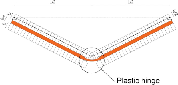
A constant interlayer thickness has, however, been assumed, ignoring necking effects, for the purpose of calculating the section capacity. The ultimate moment capacity (M₄), provided in Table 3, is then obtained by considering moment equilibrium about the plastic neutral axis, while the curvature (κ₄) is calculated from the linear strain distribution, where εg,c(σg,c/Eg) is the crushing strain of glass. As the cross-section cannot sustain any additional bending moments, a plastic hinge has formed and a mechanism developed for the simply-supported beam, as shown in Fig. 4.
Combined bending and membrane analysis
In contrast to the simple bending response of axially unrestrained beams, as presented in Sect. 3.1, the introduction of axial restraints results in a combined bending and membrane action when the deflection is sufficiently large, as shown in Fig. 5.
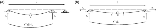
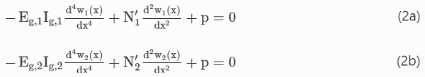
As with the simple bending analysis, the membrane stress distribution during the elastic Stages 1 and 2 can be determined by transforming the composite cross-section into an equivalent glass section (Ag). The additional contribution of the membrane stresses results in an upwards shift of the elastic neutral axis (y′₁<y₁ and y′₂<y₂) from the positions under pure bending (see Sect. 3.1). To determine the relative contribution of bending moments (M′₁ and M′₂) and membrane forces (N′₁ and N′₂), the corresponding transverse displacements (w₁ and w₂) need to be first obtained, due to the nonlinearity of the equilibrium equation arising from the introduction of membrane forces. Again, assuming full shear transfer under high strain-rates, the transverse deflection due to a uniformly distributed load (p) can be obtained by solving the fourth-order, nonlinear differential equation, derived by Aşık and Tezcan (2005) for laminated glass:
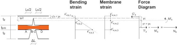
For the fully-fractured laminated glass (Stages 3 and 4), a rigid-perfectly-plastic material law is adopted for simplicity to derive the relative contribution of bending moments (M′₄) and membrane forces (N′₄), ignoring the elastic contributions of Stage 3. During Stage 4, the combination of the tensile force (T′₄), associated with the bending moment (M′4)M4′), and the membrane force (N′₄) cannot exceed the PVB tensile capacity (N₄=σpvb,c,ytpvbBpvb), as shown in Fig. 6. An increase in the membrane force will therefore cause a decrease in the bending moment and a subsequent upwards shift of the plastic neutral axis (y′₄). When the latter has reached the top of the cross-section (y′₄=0), a pure membrane response will result.
The yield condition for laminated glass, ensuring that the material law is not violated, therefore needs to account for the relative contribution of bending moments and membrane forces. Following a similar approach to that considered by Sawczuk and Winnicki (1965) for singly-reinforced-concrete, this is derived by eliminating the unknown position of the plastic neutral axis (y′₄) in the dimensionless equivalents of the bending (m) and membrane (n) equations defined in “Appendix A.1” section:

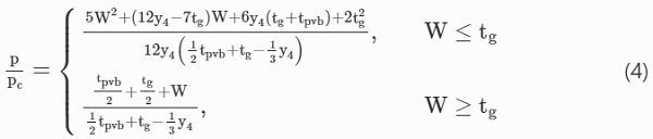
A load–displacement relationship for laminated glass beams in Stage 4 can then be derived from the above yield condition by applying the upper-bound theorem of plasticity for finite deflections on the same collapse mechanism introduced in Sect. 3.1 under simple bending, as shown in Fig. 4. This assumption, of the same initial mechanism occurring under both bending and combined bending–membrane action, is commonly adopted in plastic analysis (Jones 2011). Under a uniformly distributed load (p) and the linear velocity profile of the collapse mechanism (w˙(x)=W˙x/L/2), the load–displacement relationship for the mid-span deflection (W) is obtained by equating the external work rate
![]()
to the internal energy rate dissipated at the location of the plastic hinge (ED˙=(M+NW)θ˙midspan). Considering the collapse load (pc=8M₄/L²) for simply-supported, unrestrained laminated glass beams, the loading for axially restrained beams can be written in non-dimensional form:
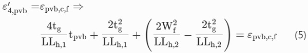
The above load–displacement relationship is valid for an interlayer with infinite ductility. Thus, the failure displacement (Wf) for PVB laminated glass can be defined by equating the total longitudinal strain in the interlayer (ε′₄,pvb) to the PVB failure strain (εpvb,c,f) defined in Sect. 2.2, with the derivation provided in “Appendix A.2” section:
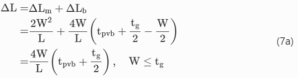
The plastic hinge length (Lh), defined in Fig. 6 as the delaminated length of the interlayer from the attached glass fragments, can be obtained from Eq. 6, as derived by Belis et al. (2008) under pure bending:
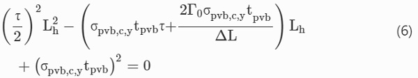
where τ is the shear stress at the interface between the interlayer and the glass fragment and Γ₀ is the fracture energy of the interface.
For midspan deflections less than the top glass layer thickness (W≤tg), a single plastic hinge is formed, as shown in Fig. 4. Thus, the above equation can be modified to also account for extension due to the axial restraint, to derive the plastic hinge length for combined bending and membrane action (Lₕ,₁):
For midspan deflections greater than the top glass layer thickness (W≥tg), a pure membrane response will occur, with the extension due purely to the large deflections under the axial restraint:

A single plastic hinge will no longer form and the entire beam will behave as a string (Jones 2011), resulting in a deformation length (Lh,₂) equal to the total delamination occurring from each crack:
![]()
where Lf is the length of each fragment.
Results and discussion
The analytical models introduced in Sect. 3 have been solved numerically for the case of simply-supported laminated glass beams with annealed glass layers (tg=6mm) and a PVB interlayer (tpvb=1.52mm), and for two different span lengths (L=200mm and 1000mm) and a constant width (B=55mm). To validate the assumed monolithic beam action under high strain-rates,and investigate the relative bending/membrane contribution under in-plane restraint, both a short and a long span are considered. The material properties considered in the analysis are introduced in Sect. 2 and the specific values used are summarised in Table 4.
Table 4 Material properties for laminated glass considered in the analysis - Full size table
Influence of high strain-rate
The moment–curvature relationship for the axially unrestrained, laminated glass is plotted separately for all Stages in Fig. 7, assuming, for simplicity, no permanent curvature at the end of each Stage, as discussed in Sect. 3.1. This allows direct comparison with future experimental results that will assess each Stage independently. The moment (M₁,M₂,M₃ and M₄) and curvature (κ₁,κ₂,κ₃ and κ₄) capacities under high strain-rates, are computed from the equations presented in Table 3. These may then be compared with the low strain-rate values, to assess directly the influence of high strain-rate. For Stages 1 and 2, the low strain-rate moment and curvature capacities are calculated for the layered limit, assuming no shear transfer in the interlayer. The elastic moment–curvature relationship is therefore used (M=EIκ), considering only the second moment of area about the centroidal axis of each glass layer
![]()
assuming that the glass layers bend as two separate beams. For Stages 3 and 4, there is no reserve capacity for low strain-rates, as demonstrated by the experimental work of Kott and Vogel (2003, 2004, 2007) described in Sect. 1, and therefore the moment–curvature relationship is not plotted.
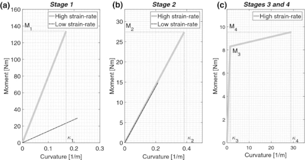
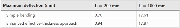
Figure 7a shows that the moment capacity of stage 1 at high strain-rates is increased by more than a factor of four compared to the low strain-rates value. This is due to the enhanced shear modulus of the interlayer at high strain-rates, resulting in the laminated glass working as a monolithic beam, with an enhanced second moment of area. This is an upper bound limit, as there may also be some shear transfer by the interlayer even under low strain-rates and therefore enhancing the layered response considered. To validate the assumption of monolithic bending under high strain-rates, the calculated maximum, mid-span deflection may be compared to that calculated using the enhanced effective-thickness approach presented by Galuppi and Royer-Carfagni (2012), which accounts for finite shear coupling between the interlayer and the glass layers.
As shown in Table 5, almost identical deflections are obtained for the larger span (L=1000 mm), while some shear deflection contributions are evident for the shorter span (L=200 mm). It is, however, noticed that the deflections in Stage 1 for the short span are limited to less than 1 mm. Considering the nondimensional coefficient η(η=0 for layered limit, η=1 for monolithic limit) introduced by Galuppi and Royer-Carfagni (2012), it can be concluded that, for large spans (η=1 for L=1000 mm), a monolithic beam assumption is valid for laminated glass beams under blast loading, while for shorter spans (η=0.93 for L=200 mm) the contribution of shear deflections should be accounted for.
Table 5 Comparison of mid-span deflections for high strain-rates under simple bending and the enhanced effective-thickness approach presented by Galuppi and Royer-Carfagni (2012) - Full size table
In Stage 2, as expected, the almost identical response shown in Fig. 7b for high and low strain-rates indicates that the PVB contribution to bending is negligible, and the entire bending resistance is provided from the remaining unfractured glass layer. The increased moment capacity under high strain-rates results from the enhanced fracture strength of glass. Finally, for Stages 3 and 4, the effect of high strain-rate, compared to the negligible capacity under low strain-rates that is not plotted, is clearly visible from Fig. 7c, which shows the residual post-fracture bending capacity. This resembles the low strain-rate response of stiffer interlayers, such as ionomers or added steel-wire mesh reinforcement, as experimentally demonstrated by Delincé et al. (2008) and Feirabend (2008) respectively.
The moment capacity for Stage 3 shown in Fig. 7c represents a lower bound solution, as the material properties introduced in Sect. 2.2 are for a uniform cracking pattern with a 10 mm glass fragment length. This assumption implies that all cracks are aligned between the two glass layers and therefore a series of rigid and flexible sections are present along the length of the beam. If the cracks are not aligned, a higher Young’s modulus and yield strength will result, as reported by Nhamoinesu and Overend (2010), who compared the results from through-crack and offset-crack uniaxial tensile tests on laminated glass specimens with a single crack under low strain-rates. A similar conclusion was also reported in the analytical model for out-of-plane bending of fractured laminated glass under low strain-rates presented by Galuppi and Royer-Carfagni (2018). The drawback of cracks that are not aligned, however, is a more brittle failure with almost no residual plastic capacity (Nhamoinesu and Overend 2010). In this case, Stage 4 may never develop. The anticipated fracture pattern under blast loading, and its consequences for the analysis presented here, is reserved for future work.
Another useful comparison can be made with reinforced concrete beams, which also consist of a brittle material (concrete) reinforced with a ductile material (steel) to carry tension. Although the same methodology is applied to evaluate the moment capacities of the cross-section for each Stage (the transformed-section method for the elastic stage and moment equilibrium for the ultimate moment capacity), it is evident that the moment–curvature response is quite different. In laminated glass, the residual, post-fracture plastic moment capacity of Stage 4 is smaller than the pre-fracture moment capacity of Stage 1, while in reinforced-concrete the ultimate plastic moment capacity is larger than the uncracked moment capacity. The upper-bound theorem of plasticity, frequently applied in the structural analysis of reinforced concrete beams and slabs (BS EN 1992 2004), would therefore not result in efficient designs for axially unrestrained, laminated glass beams due to the rigid-plastic material law approximation that ignores the elastic contributions.
Influence of in-plane restraint
The elastic, mid-span deflections (Stages 1 and 2) under simple bending and combined bending–membrane action for laminated glass are shown in Fig. 8 for both the short and long span beams. To derive the combined bending/membrane deflections under in-plane restrained boundary conditions, Eqs. (2a) and (2b) have been solved with the Galerkin method, considering an approximate, sinusoidal deflected shape (Wierzbicki 2013). The maximum deflections of each Stage were calculated iteratively numerically, by limiting the total longitudinal tensile stress (the sum of bending and membrane stresses) to the tensile fracture strength of glass under high strain-rates given in Table 1. These were validated with the solutions presented by Timoshenko and Woinowsky-Krieger (1959), which assumes cylindrical bending rather than the sinusoidal form assumed here.
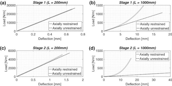
Figure 8 shows that for short spans, the entire response is governed by bending in Stage 1, with small membrane contributions evident in Stage 2. In contrast, for large spans, membrane contributions are also evident in Stage 1, resulting in smaller deflections compared to simple bending. It is clear that membrane action dominates the response in Stage 2. In addition to smaller deflections for the larger span, the presence of axial restraint enhances the load capacity by factors of 1.4 and 4.8 in Stage 1 and 2 respectively. This means that the laminated glass can resist a significantly larger load before fracture, compared to the unrestrained boundary condition. To develop such large membrane forces, however, the connection details and the supporting frame must also be adequately designed to ensure that they can resist the horizontal reaction forces developed.
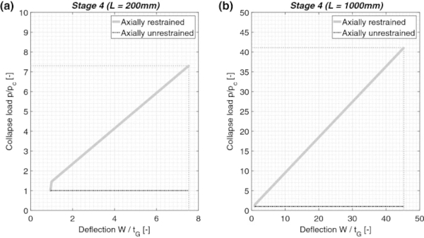
The load–displacement relationship for Stage 4 is shown in Fig. 9. The midspan deflection is calculated by solving Eq. (4) numerically, and nondimensionalised by dividing by the top glass layer thickness. The failure deflection, at which tearing of the interlayer occurs, is given by Eq. (5), assuming an arbitrarily delamination length of 8 mm, as the solution of Eq. (6) resulted in delaminated lengths greater than the assumed glass fragment length, thus causing glass fragmentation. This assumption requires further investigation by experimental testing. However, it is considered conservative for the current study, as a shorter plastic hinge will result in larger strains. For predicted deflections that are comparable to the span lengths, the validity of the small angle approximation and binomial expansion, considered in the development of the analytical models in Sect. 3.2, requires further investigation.
The linear relationship observed in Fig. 9 for nondimensional deflections greater than 1 indicates the pure membrane response, with the combined bending/membrane action limited to deflections less than the top glass layer thickness, as described by Eq. (4). This results in significant enhancement of the post-fracture capacity, compared to the collapse load of unrestrained laminated glass. Additionally, it is also observed that this is higher than the fracture load of the intact panel in Stage 1, highlighting the important contribution of axial restraint in the reserve, post-fracture capacity.
This conclusion is in agreement with the low strain-rate, pressurised water tests of laminated glass panels presented by Morison (2007) and Zobec et al. (2014), who recorded post-fracture loads in excess of the unfractured capacity and a dominant membrane response. It should be noted, that the analysis presented here considers tearing to result only from combined bending/membrane strains and has ignored the possible rupture of the interlayer caused by the attached glass fragments, although the latter has been observed in practice, such as in the water bag tests performed by Zobec et al. (2014).
Conclusions
This theoretical study has adopted a ‘first-principles’ approach to assess the effects of high strain-rate and in-plane restraint on the structural response of PVB-laminated glass. A review of the material behaviour of glass and PVB has shown that the salient material properties are enhanced significantly under the high strain-rates associated with blast events. Analytical models for laminated glass have been developed, which describe the four stages of quasi-static response from initial loading to failure. These indicate that the enhanced material properties have a significant effect on the moment and curvature capacities of the glass in simple bending. Specifically, the results have shown that, for high strain-rates, the enhanced shear modulus of the PVB justifies a monolithic beam approach to panel analysis. Furthermore, the enhanced modulus results in significantly enhanced moment capacities of each stage, including a residual post-fracture bending capacity that is considered negligible for low strain-rates.
The incorporation of in-plane restraint results in combined bending–membrane action under large deflections. A significant membrane contribution to the panel response, and therefore reduced panel deflections, is observed in the elastic stages of long-spans, while for short spans, the effects are less pronounced. For the post-fracture stage, a yield condition has been developed to determine the relative contribution of the internal forces, without violating the material law, and the upper-bound theorem of plasticity applied to determine the collapse load corresponding to interlayer tearing. Membrane action has been seen to dominate the response for both span lengths, resulting in enhanced collapse loads greater than the capacity of the intact laminated glass.
Experimental data for the quasi-static response of laminated glass under high strain-rates are not currently available. Future work should therefore include experimental validation of the analytical models introduced here. Additionally, the inertial effects associated with dynamic loading, which have been ignored in this paper, should also be considered, to provide a complete theoretical framework for the blast response of laminated glass. Finally, the extension of the beam models to two-way spanning plates, that represent a more realistic geometry of glazed facades, should also be pursued.
References
Acknowledgements
The first author gratefully acknowledges the Engineering and Physical Sciences Research Council (EPSRC) for funding this research through the EPSRC Centre for Doctoral Training in Future Infrastructure and Built Environment (FIBE CDT) at the University of Cambridge (EPSRC Grant Reference No. EP/L016095/1). The contribution of the Institution of Civil Engineers, through the ICE Research and Development Enabling Fund, is also gratefully acknowledged.
Author information
Authors and Affiliations
Department of Engineering, University of Cambridge, Cambridge, UK - Socrates C. Angelides, James P. Talbot & Mauro Overend
Corresponding author
Correspondence to Socrates C. Angelides.


.")