This paper was first presented at GPD 2023.
Link to the full GPD 2023 conference book: https://www.gpd.fi/GPD2023_proceedings_book/

Authors:
- Iris Rombouts - Octatube
- Koos Fritzsche - Octatube
Abstract
A stately, neo-Renaissance office building from 1915 houses Shell’s headquarters in The Hague, The Netherlands. As part of a largescale renovation, a state-of-the-art structure is welcomed to the premises: one of the monumental courtyards is covered with a gridshell. The dome-shaped gridshell is covered with glass panels cold twisted on-site to reduce the amount of energy combined with a better visual quality compared to warm bended glass. The glass and therefore grid size is defined as a result of a meticulous, parametric game: the perfect balance is sought between maximal stiffness for external load and minimal stiffness for cold twisting of the glass. The exercise increased the grid size from 1.6m to 2.6m reducing a large amount of material.
Where old meets new, challenges arise: no forces can be exerted perpendicular on the perimeter of the monumental courtyard, resulting in sliding connections in a horizontal direction. Moreover, during installation the structure may not rest on the scaffold. This brought another challenge to the table, as the only remaining connection to the existing structure is the ring beam. For this reason, the roof is divided into the largest possible selfspanning frames, with the limiting factors of transport and coating in mind. After installing these frames, in the centre of the roof a square-shaped gap of 21x21m remained that was filled up with a reciprocal frame division, installed with two cranes simultaneously.
1. Introduction
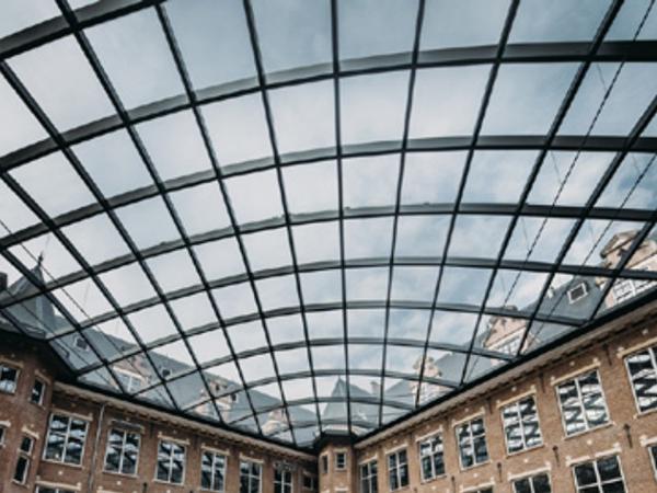
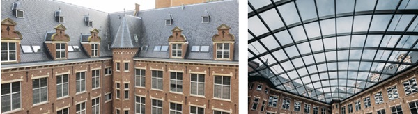
In 1915, the first brick was laid for the head office of the Batavian Petroleum Company, one of Shell's predecessors. A stately office building was built, whose style recalls the Dutch architecture of the 16th and 17th centuries. Although the classical façade suggests otherwise, the interior of the office was ultra-modern for its time. The complex - also known as C30 - underwent a large-scale renovation. An eye-catching feature is the state-of-the-art roofing of one of the monumental courtyards. Old and new are literally connected to each other here. Octatube was approached in an early phase of the design to help optimise and eventually construct the design. Lessons learned from the Diamond-exchange building in Amsterdam (Fritzsche et al. [1]) provided a firm starting point.
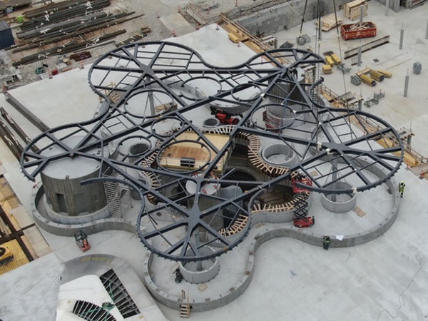
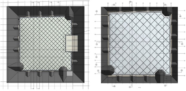
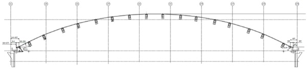
Despite the courtyard appearing to be squared, in practice it is not perfectly square shaped (see Figure 2) and therefore each particular component is unique. The dome-shaped gridshell consists of a double curved steel grid of approximately 30x30 meters with a height of 3.5m. Both the edge beams and the grid profiles are designed as rectangular hollow sections. The curved steel grid is covered with 141 insulated glass panels of ca. 2.6x2.6m which were cold twisted on site, therefore every pane needed to be a unique parallelogram. The grid size is defined as a result of a meticulous, parametric optimization game: the perfect balance for the glass is sought between maximal stiffness for external load and minimal stiffness for cold twisting.
2. Engineering of the geometry
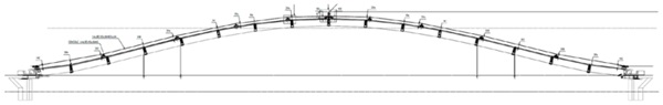
The first step in the realisation of this complex roof was studying and optimizing the shape. After multiple variants of geometry the end result was a spherical shape combined with straight edges in a parallelogram. As a result of these straight edges, the inclination of the roof varies over the edge from steep at the centre of the straight edge to gentle in the corners (see Figure 3).
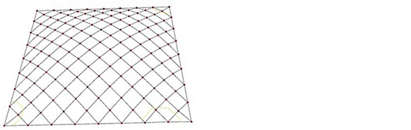
Various grid divisions have been considered during the design phase. The design came to Octatube with a grid division of ~1.6m and left with ~2.6m (see Figure 2): a large amount of material was reduced. The optimization was a game of engineering and structural design: a balance was sought between the largest possible glass combined with the least amount of steel (minimum weight on the existing structure) and the boundaries of cold twisting of the glass combined with live loads on the glass. The bigger the glass, the more twisting is needed to stay within the shape and higher stresses will occur due to a bigger surface for live loads.
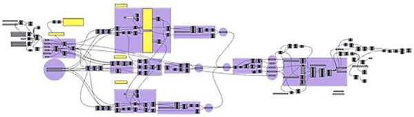
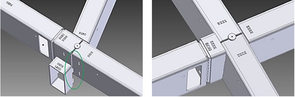
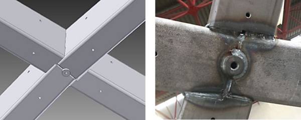
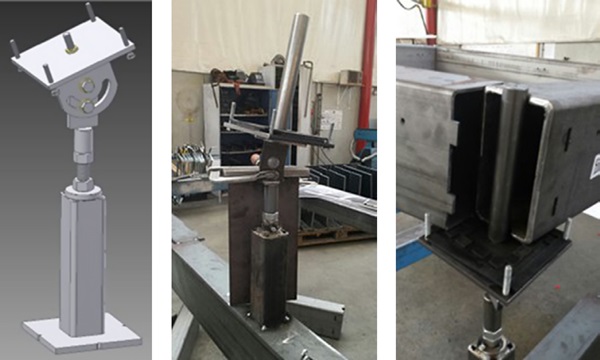
The final shape was defined with a parametric computer model in Rhino in combination with Grasshopper. Every connection of lines in this parametric model became a node and got a unique number. From that moment on, until the end of the production, this node was an important basepoint at the top of the structure. In practice it is developed into a circular rod element in the centre of the node (see Figure 7). Once the node was defined in the model, it got a set of parameters.
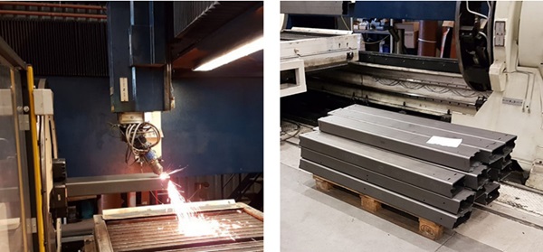
All 425 profiles in between the 150 unique nodes have a different length and angular rotation in multiple directions with respect to the connection profiles due to the shape of the grid. Therefore, each profile must be uniquely cut at the ends to allow for a welded connection. To prevent confusion in the grid production, a clever digital design was required. Using an in-house developed script, a file-to-factory method was implemented to generate 2D and 3D files of each unique element which contain all relevant information for that element. All these files were then directly sent to a 3D laser cutter ensuring the profiles have unique shapes on both ends, including numbering and weld pre-cuts.
Some of the nodes are welded nodes, others are a combination of welded and bolted connections (see figure 7 and 8). To make a clever fit of the steel and to make the best use of the 3D laser technology, a ‘male-female’- connection was implemented: one part has two protruding small pieces of material, while the connecting one has two holes for it (see figure 7). Further optimization of the manufacturing process has been achieved through the accurate organization of the produced steel profiles. The individual parts required for each frame element were produced and packed in the right order of fabrication and had numbers which correspond with the node numbers (see figure 7).
This method of digital design using the benefits of 3D laser cutting has led to an efficient and accurate production and installation.
3. Structural design
3.1 Monumental building and corresponding boundaries
3.1.1. Roofs perimeter
The dome structure behaves like a 3D arch structure: under the influence of a downward load on the roof, the arch becomes flatter in a way that make the ends move outwards. The higher the dome structure, the less this deflection and movement at the ends is. The height of this dome was prescribed in an early stage of the design based on aesthetic proportions. The horizontal forces at the ends generated by the imposed horizontal movement are usually absorbed by the connection of the surrounding building. But in this case, no forces may be exerted perpendicular on the perimeter facades of the courtyard, nor bending moments. This resulted in 31 hinged connections between the edge beam and the monumental concrete structure, which are able to slide in horizontal direction.
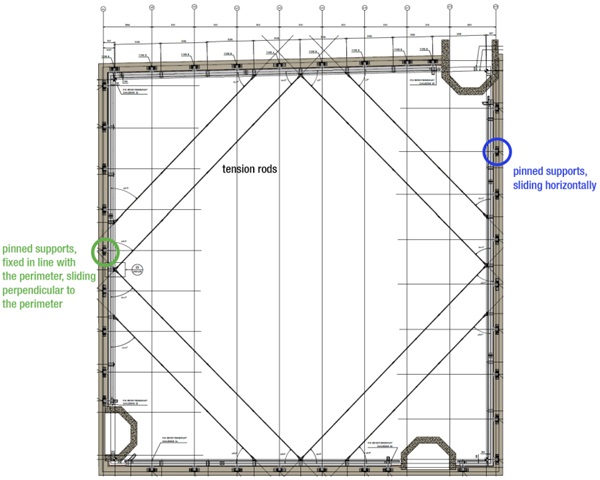
In order to fix the roof for horizontal wind loads, 4 connections (at a central position of each façade) are fixed in line with the façade, but still sliding perpendicular to the façade (see Figure 9). By doing this, the roof is also able to ‘breathe’ under thermal loading.
Another way to absorb the horizontal forces as a result of vertical loading, is to make use of a continuous ring beam which is subjected to tension when the roof wants to flatten. As one can imagine, a gridshell is like an inverted colander: the continuous edge holds the dome shape together. The perimeter of the monumental courtyard however includes three turrets, which interrupt the continuous edge of the gridshell. Therefore the crucial edge beam could not be designed as a continuous ring beam, but needs to be kept in balance by tensions rods.
3.1.2. Reciprocal frame
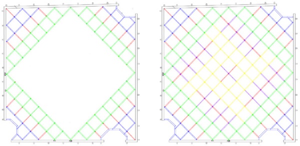
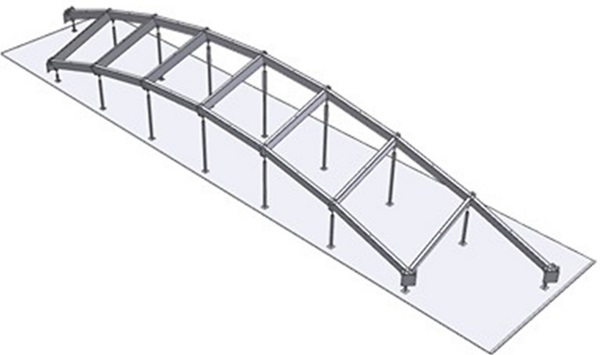
The monumental courtyard is carried by a basement structure, which is not able to take any loads during installation. Therefore, it was not allowed for the steel structure to rest on the scaffold. Since the only remaining connection to the existing structure is the ring beam, the steel grid is divided into the largest possible self-spanning ladder frames, with the limiting factors of transport and coating in mind. The green marked frames shown Figure 10 have length of approximately 20m. They have similar dimensions, but are not equal due to the shape of the roofs perimeter.
In the centre of the roof, a square-shaped gap of 21x21m (in between the green marked frames in Figure 10) is filled up with a selfsupporting reciprocal frame division. Four frames, marked in yellow are bolt connected to each other and to the green frames without making use of any downward support.
3.2 Rotational stiffness
The connections between multiple welded frames are bolted and therefore have a specific rotational stiffness. To verify the structure on strength, stiffness and stability two models have been made to set the (upper and lower) boundaries regarding stiffness of the connections. In the first model, the connections are infinitely stiff in order to check whether the connections do have enough resistance in strength. The second model includes specific rotational stiffness to check stiffness and stability of the structure. The stiffness of the connections in the end determines the load distribution across the roof and therefore the design of all connections.
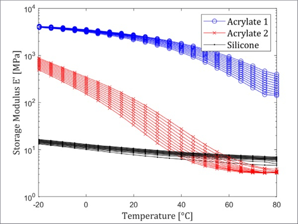
3.3 Cold twisting of glass
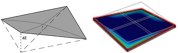
All glass panels are produced as flat panels and twisted in shape on site to reduce the amount of energy, combined with a better visual quality compared to warm bended glass. To realize this, clamping plates are used at the corners of the glass.
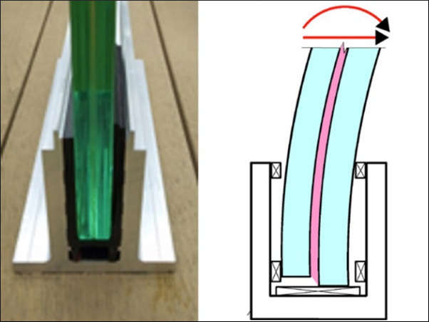
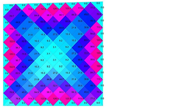
As shown in Figure 11 the torsion in the glass is at its highest in the centre of the edges. This maximum value for torsion determined the glass thickness and indirectly the shape and grid distribution of the canopy.
Accurate structural calculations validated the maximum deformation of 126mm due to torsion occurring in the roof. This means that one corner is put up or down 126mm, while the other 3 are in the same surface. This results in a double-curved glass surface, following the free-form shape of the roof.
4. Production
For a roof that consists of many unique parts, prefabrication is an ideal method. The dimensions can be closely monitored and deformations that may play a critical role during the assembly can be identified. This allows for high assembly speed on site. Additionally, welds and finishes applied in controlled environment achieve a higher and more constant quality.
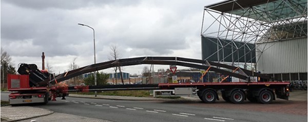
As mentioned earlier, maximum sized ladder frames are prefabricated in Octatube’s workshop in Delft. To get the right position of every node in six degrees of freedom, an adjustable jig was designed. This jig was put in the exact position for every frame with the right rotational angles creating the centre point of the node by means of a circular rod. An extra-long transport method was used to transport the biggest frames to the coating company and to site.
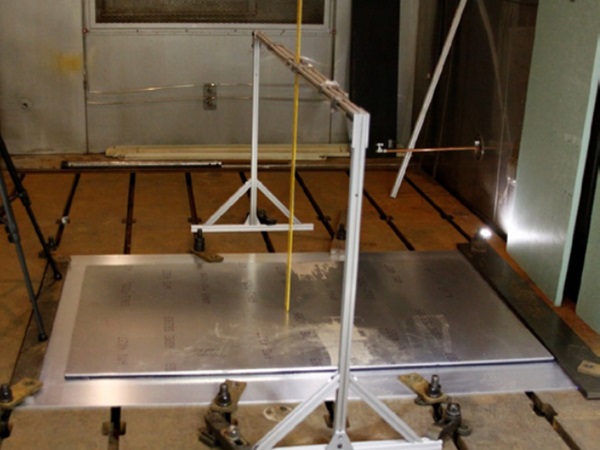
A standard glazing system with secondary waterway was installed on the steel grid below the glass. Normally, these systems are used for straight structures, like flat facades or flat/pitched roofs. Therefore, for this application, besides impact tests also airand watertightness tests were done on a test mock-up to validate the system.
To improve the aesthetics but also test and tweak the production and installation methods, also a visual mock-up was built in an early stage of the project. This mock-up consisted of a corner of the roof with 3 glass panels and most of the final detailing in.
5. Installation
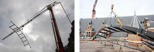
The installation started with the edge beam with its sliding brackets installed, then the tension elements were put in position. This stable boundary was the basis to start assembling the steel grid inwards from the perimeter. To explain the installation sequence of the steel grid, reference is taken to Figure 10. The four big green marked ladder frames were installed first. Two from one side of the building, two from the other side, to reach the smallest crane flight for a 3000kg frame. After these self-spanning elements, the blue corners were installed to further stabilize and fix the final position of the edge beam from its initial fixation on sliding supports only.
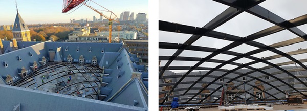
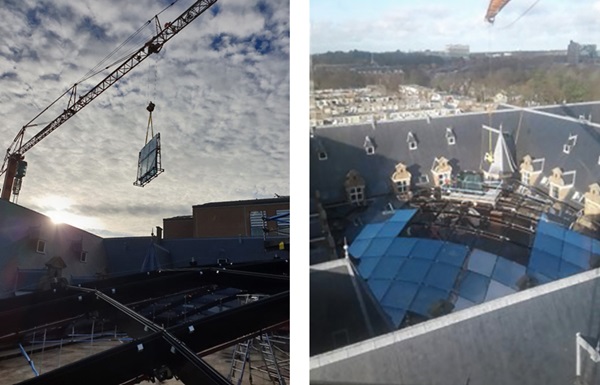
After the blue and green elements, the red beams in between those elements were placed to finalise the corners. With these elements installed, the most complex action of the installation took place: hoisting the yellow marked reciprocal frames. Every frame has a length of 16m and all four frames need to be placed in one day, because only the four frames together create a self-spanning, stable structure. This action was carried out with two cranes simultaneously: one crane holding the first frame for the entire day in position, the second crane connected the other three frames to it one by one in a counter clockwise direction.
Despite the complexity of the roof structure and its installation, everything fits perfectly due to the precise prefabrication of the frames. All frame connections were bolted onsite and not a grinding tool had to be used. This made it possible to install the entire steel roof in just two weeks.
For installation of the glass, a custom loading platform was designed specially for this project which was hoisted on the steel structure. This platform allowed for one glass stillage with maximum six glass units. From this platform, the glass units were installed with a double system vacuum lifter. With this method, not every glass pane needed to be hoisted separately over the entire building, but made just a short flight.
The sequence of installation of glass units was such that the steel structure was loaded gradually: starting with the corners and once the corners were filled, making a snail shell to the top of the roof. Finally, the loading platform was removed and the last four panes were installed directly from street level to the top of the roof.
Octatube delivered this roof in March 2021.
6. Conclusion
Realizing new architecture in a monumental building is challenging by definition. Sometimes all the crucial preconditions are known in advance, but usually a number of them appear during the process. By introducing an integral, multidisciplinary working method at an early stage, all challenges were early identified and tackled. With all disciplines (design, engineering, production, assembly) involved, crucial questions were asked and included in the joint development of possibilities and solutions. The sooner you put heads together, the sooner you will have all necessary information to come up with smart solutions.
7. Acknowledgements
We thank client Shell for this challenge, main contractor De Vries en Verburg for frequent and efficient collaboration, Octatube’s design and assembly team, Octatube’s subcontractors and suppliers.
8. References
[1] Fritzsche K., van der Sluis W., Smits E. and Bakker J., Capital C, Geometric Optimization of a Free-Form Steel Gridshell Towards Planar Quadrilateral Glass Units. Challenging Glass 7, conference of Architectural and Structural Applications of Glass, 2020.