This paper was first presented at GPD 2019 by Viviana Nardini from Sika Services AG and Florian Doebbel from Sika US.
ETAG002 and ASTM C 1401 are the main international Standards providing regulations for design of silicone joints in Structural Sealant Glazing (SSG) applications.
They provide calculation methods with reference to flat glass units with regular shape, in vertical position, bonded along all sides to load-bearing profiles, experiencing limited deflections and subject to wind load, dead load and temperature variations.
Aforementioned Standards do not provide any recommendation for design of SSG joints in other system configurations, which are wellestablished solutions in the façade industry. It is the case, among others, of elements which are inward and outward sloped, not bonded along all sides, flat as well as curved and with irregular shape and subject to different load types (e.g. barrier loads, snow loads, maintenance loads, blast loads, etc.).
In this paper, an advanced calculation method developed by Sika is presented to design SSG joints exposed to any kind of stress (tensile, shear and bending). Such calculation method correlates the strength offered by the adhesive to the duration and simultaneity of any load applied with the result of being applicable to any system configuration. The experience gained by Sika on projects is shared with practical examples.
1 Introduction
Structural Sealant Glazing (SSG) is a wellestablished technology successfully applied for more than 50 years in the façade industry. Since 1970s – 1990s simplified equations have been implemented in international Standards as ETAG002 [1] and ASTM C 1401 [2] to regulate the design of SSG joints bonding glass panels to metallic framing.
Such Standards provide effective rules for typical façade systems consisting of vertical glass units with rectangular shape, bonded along all sides, mechanically supported or unsupported, experiencing limited deflections and subject to wind load, dead load and thermal variations.
In the last decades, available technologies have developed significantly in the façade industry, increasing the complexity of the projects and challenging the design of SSG joints applied in new system configurations and load conditions. Among others, it is the case of elements which are inward and outward sloped, not bonded along all sides, curved or with irregular shape, subject to barrier loads, snow loads, blast loads, maintenance loads, etc.
Today, it is very clear to façade engineers that the rules provided in the available Standards are effective but very limited in their scope. New calculation methods, design requirements and performance limits must be set to answer the actual needs of the market without any compromise in safety.
This paper presents an advanced calculation method developed by Sika to design SSG joints exposed to any kind of stress (tensile, shear and bending) and being applicable to any system configuration and load condition. The calculation method proposed herein is currently under discussion within CEN/ TC349/WG2 for upgrade of current Standard procedures.
2 Dependency of the SSG joint strength on the load duration
The strength offered by a silicone joint depends on the duration of the load applied. For this reason, ETAG002 [1] identifies the following adhesive strengths:
• The dynamic tensile strength σdyn, defined
as
σdyn = RUT,5 / γtot
where:
RUT,5 is the characteristic ultimate tensile strength of the adhesive γtot = 6 is the total safety factor RUT,5 value is obtained from tests performed on H-specimens with joint dimensions 12mm x 12mm x 50 mm (Fig.1), tested in tension at the speed of 5 mm/min.
This strength is used to determine the bitedimension of the SSG joints loaded by wind.
• The dynamic shear strength τdyn, defined as τdyn = RUS,5 / γtot
where
RUS,5 is the characteristic ultimate shear strength of the adhesive
γtot = 6 is the total safety factor RUS,5 value is obtained from tests performed on H-specimens with joint dimensions 12mm x 12mm x 50 mm, tested in shear at the speed of 5 mm/min.
This strength is used to determine the thickness of the SSG joints due to thermal dilatations.
• The static shear strength τstat, defined as
τstat = τdyn / γc
where
γc ≥ 10 is a creep factor
Additionally, the creep test described in Section 5.1.4.6.8 of ETAG002 [1] is used to control that the static shear strength adopted ensures the elastic behavior of the joint after being stressed under permanent shear and simultaneous dynamic tensile loads, while limiting creeping phenomena.
In unsupported systems, the static shear strength is used to determine the bite dimension of the SSG joints loaded by the glass weight.
![Fig. 1 – Dynamic tensile strength from tests on H-specimens with joint dimensions 12 mm x 12 mm x 50 mm [1].](/sites/default/files/inline-images/Fig1_90.jpg)
Despite no clear definition of static tensile strength σstat is given by ETAG002 [1], the creep factor definition could be used to define it as σstat = σdyn / γc.
The static tensile strength can be used for example to determine the bite dimension of SSG joints loaded by the glass weight in outward sloped façade elements.
The approach given by ETAG002 [1] allows to define both the dynamic and static tensile and shear strengths of an SSG adhesive. However, it does not provide clear answers to the following basic questions:
• What is the load duration associated to a “dynamic” and “static” load?
• What is the strength that can be used for a load duration other than wind or glass weight, which are respectively considered as “dynamic” and “static” loads by [1]?
• How to define the dimensions of a joint loaded by actions of different duration? E.g. How to define the final dimension of SSG joints loaded by wind, snow and maintenance loads in an unsupported and outward sloped element?
To answer to these questions, at first it is important to define the duration of all loads applied to the SSG system.
Typical durations considered in façade design are:
t ≤ 5 sec - wind load
t ≤ 1 min - barrier load
t ≤ 1 day - maintenance load, climatic load
1 week ≤ t ≤ 4 weeks - snow load
t ≥ 90 days - dead load, cold bending load
When the load duration is very short and impulsive, usually the deformation speed of the joint become more relevant:
1.0 m/s ≤ s < 6.0 m/s - blast load
Of course, the load durations and deformation speed estimated above must be defined on project base.
When the duration of each load applied to the SSG system is identified, the strength offered by the SSG adhesive for each load duration can be tested and defined.
Table 1 provides a summary of the design strengths offered by Sikasil® SG-500 and Sikasil® SG-550 structural silicone, depending on load duration or deformation speed. The values refer to tests performed on joint with section 12mm x 12 mm, which are the standard sample dimensions used by ETAG002 [1] for strength definition.
3 Load combinations and timeframe-dependent stress check
After the load durations and design strengths offered by the SSG adhesive are defined, proper load combinations must be identified. At first, different timeframe durations can be set; then, the loads that can simultaneously apply in the specific timeframes must be combined.
EXAMPLE:
Considering an inward sloped unsupported system where SSG joints are stressed by wind, dead load and snow load, the following load combinations can be defined.
• Timeframe > 90 days
LC1: dead load
• 7 days < timeframe ≤ 21 days
LC2: dead load + snow load
• Timeframe ≤ 5 sec
LC3: dead load + α3 snow load + β3 wind load
LC4: dead load + α4 snow load + β4 wind load
Where αi and βi are load combination coefficients taking into account for the probability of simultaneous occurrence of the loads, as defined by project specifications and local standards.
Target is to (1) identify the relevant timeframes/ durations of the loads and (2) define the relevant load combinations associated to each timeframe, which include all loads that can simultaneously apply in the same timeframe.
For each load combination, the stress introduced into the SSG joints must be calculated and compared to the strength offered by the adhesive depending on the load duration.
Finally, for each load combination the joint utilization level must be checked as follows.
For each time frame i and load combination LC:
µTension = (σ1,i + σ2,i + … + σn,i) / σDesign_i ≤ 1.0
µShear = (τ1,i + τ2,i + … + τn,i) / τDesign_i ≤ 1.0
µ = µTension 2 + µShear 2 ≤ 1.0
where σi and τi are the tensile and shear stress on the SSG joint in the timeframe i considered for the specific load combination and σDesign_i and τDesign_i are the reference design strengths to use in pure tension and pure shear for the specific load duration.
Section 6 provides a practical example using the calculation method described above.
4 Bending stress
ETAG002 [1] defines the following boundary conditions:
- The SSG joint bite h must be bigger than its thickness e, to ensure the joint behaves as a structural stiff connection.
- The joint bite h must be maximum 3 times its thickness, to ensure the joint behaves as a pure hinge connection. If b>3e, bending stress are transferred to the joint which behaves neither as pure hinge nor fully restraining connection.
- The maximum deflection of the bonded glass unit must be limited to Lmin/100, with Lmin being the shortest side length of the glass element. For bigger panel deflections, bending is transferred to the joints.
Overall, ETAG002 aims at designing the SSG joint as a pure hinge. On the other side, rules to control the bending stress transferred to SSG joint are required in façade design on daily base.
When big panel deflections occur or when joint ratio bite : thickness is bigger than 3, the bending stress transferred to the joint can be calculated based on following relationship:
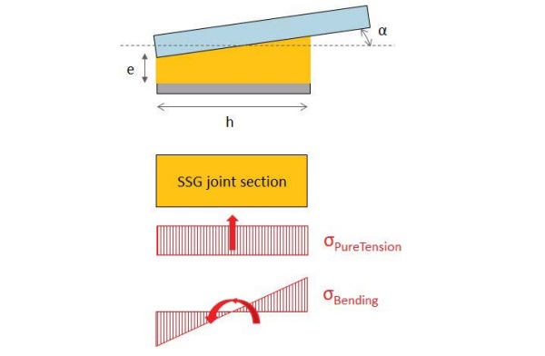
σBend = h α Ebend / (2 e) Tensile bending stress with:
h = joint bite
α = rotation of the glass edge at the bonded support
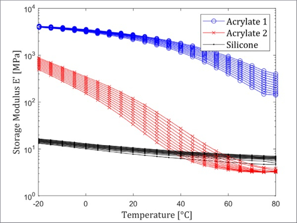
Ebend = elastic modulus of the adhesive for bending
e = joint thickness
For 4-sided bonded rectangular glass panel:
α = 3.2 f / Lmin
with:
3.2 = form factor
f = maximum displacement in the middle of the panel
Lmin = length of the shortest side
In many system configurations, the design includes a sub-frame connected by hinges to load-bearing profiles (Fig. 2). To ensure the stability of the overall static scheme, a bending moment M must be transferred to the SSG joints of the glass panel bonded to the sub-frame. In such cases, the bending tensile stress can be calculated as follows: σBend = M / W = M / (h²/6)
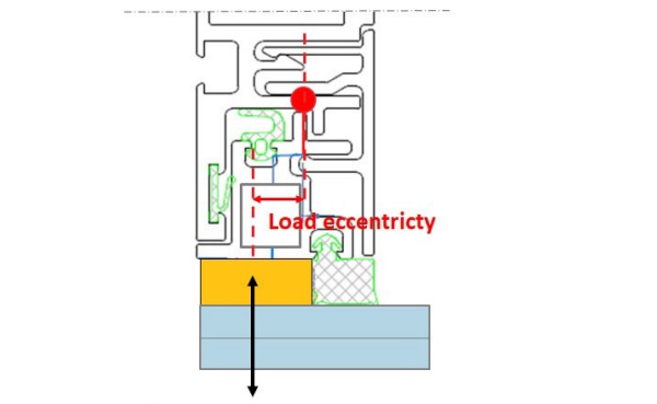
It must be observed that a bending moment introduces peak stress into a joint section, according to the typical stress distribution simplified in Fig. 3.
Such stress distribution is completely different than the one assumed by ETAG002 [1] for transfer of pure tensile forces. Indeed, ETAG002 [1] considers:
• the joint as a hinge
• the tensile stress into the joint as uniform within the section according to the simplified equation σ = Tensile force / Area (Fig.3)
• the tensile strength offered by the joint derived from the ultimate tensile force RUT,5 obtained by testing in pure tension H-specimens with joint 12 mm x 12 mm.
In order to evaluate the bending stress introduced into the joint, a new adhesive tensile strength must be defined.
Indeed, it would be very conservative to compare the peak stress due to bending with the average tensile strength obtained from pure tension on H-specimens (Fig. 1).
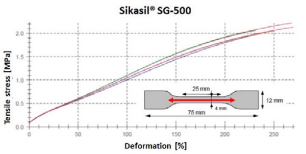
Instead, the peak stress could be correlated to the average tensile strength offered by dumbbell samples 2mm thick and 4mm wide tested in tension (Fig. 4). In other words, the local peak stress can be correlated to a pure material strength.
Considering a reduction factor of 6, the dynamic bending tensile strength offered by Sikasil® 500 and Sikasil® SG-550 is 0.36 MPa and 0.56 MPa respectively.
Novartis project built in New Jersey by Gartner [3] can be used to validate the concept outside small-scale tests.
The typical facade detail consists of vertical glass fins more than 9m high and approx. 0.93m spaced, bonded by Sikasil® SG-550 to U-profiles as per Fig. 5. To minimize the dimension of the vertical mullions, the stiffening contribute provided by the inertia of the glass fins has to be taken into account; for this purpose, the structural function of the SSG joints is crucial.

To evaluate the façade deformations and check the dimensions of the SSG joints, a FEM analysis was implemented; indeed, simplified equations cannot be used when the stiffness contribution of all elements has to be evaluated.
By simulating the SSG joints by volume elements and hyperelastic law, peak stress in the joint could be calculated.
According to the design concept proposed above for limiting peak stress into joints, a maximum stress of 0.56 MPa could be allowed for Sikasil® SG-550; such strength limit was defined based on a ultimate strength of 3.4 MPa obtained from tensile tests on dumbbells and reduced by a factor of 6.
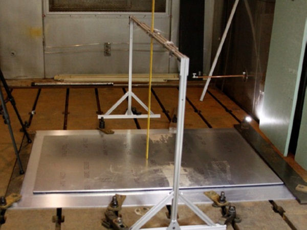
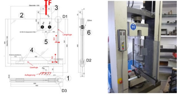
To validate the FEM analysis and system design, a mock-up test was performed reproducing the system and the expected loads (Fig. 6). According to the FEM analysis, a maximum stress of approx. 3.6 MPa could be predicted into the joint applied in the corner area when the force F in the mock up reached the value of approx. 40 kN (Fig. 7).
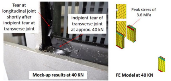
The mock up test fully validated the prediction. Indeed, when the test load reached the value of approx. 40 kN, some tears appeared in the corner location where the FE model showed the maximum stress of 3.6 MPa, which is a value very close to the ultimate strength of 3.4 MPa provided by Sikasil® SG-550 dumbbell tests.
As a consequence, designing the joint allowing a maximum peak stress of 0.56 MPa based on a reduction factor of 6 applied to dumbbell ultimate strength could allow for a design in line with the safety requirement defined by ETAG002, beyond its design rules. The mock-up results can be used as validation of the design concept proposed, correlating bending and peak stress to dumbbell tests, without any compromise on the final safety level.
5 A new advanced calculation approach
Section 2 clarifies that the pure tensile and shear strength offered by a SSG joint must be correlated to the duration of the loads applied. For this purpose, different load combinations related to different timeframes must be defined (Section 3). After calculating the stress transferred to the SSG joint for each load combination, this can be compared to the strength offered by the adhesive, which is loadduration-dependent (Table 1).
Finally, for each load combination the joint utilization level must be checked according to the Equations provided in Section 3.
Whenever a bending stress is also introduced into the SSG joint, all following relationships must be satisfied:
For each time frame i and load combination:
µTension = (σ1,i + σ2,i + … + σn,i) / σDesign_i ≤ 1.0
µShear = (τ1,i + τ2,i + … + τn,i) / τDesign_i ≤ 1.0
µ = µTension ² + µShear ² ≤ 1.0
µTension+Bending = (σ1,i + σ2,i + … + σn,i + σBending,i) / σDesignBending_i ≤ 1.0
µBending = µTension+Bending ² + µShear² ≤ 1.0
Equations above ensures that for different timeframes and load combinations, both the average stress and the peaks stress transferred to the joint section are properly controlled, ensuring a global safety factor of 6. Comprehensive tests to define the tensile bending strength σDesignBending_i offered by Sikasil® SG adhesives depending on different load durations are ongoing.
6 A practical example
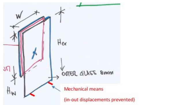
The advanced calculation approach presented in this paper was used to design the secondary sealing joints made by Sikasil® IG-25 HM Plus for the IG units sketched in Fig. 8.
The IG units consist of a laminated glass pane composed by two glass layers 6 mm thick with dimensions 1482 mm x 4345 mm (width x height); the outer glass pane consists of a monolithic glass 8 mm thick, with dimensions 1482 mm x 5052 mm (width x height). A bottom part 707 mm long is cantilevering for the outer pane. The dead load of the outer pane is not supported mechanically, but transferred via Sikasil® IG-25 HM Plus joints.
The IG units are inward sloped, with maximum inclination of 8° from the vertical axis. The following loads apply to the IG joints:
• Wind load (pW=1.75 kPa on facade; the wind load shearing factor between inner and outer glass pane is 0.50)
• In-plane dead load component of the outer glass pane (FDL_in=1.46 kN)
• Out-of-plane dead load component of the outer glass pane (FDL_out=0.21 kN)
• Climatic load (the effect of the isochoric pressure on IG joints is pCL=0.45 kPa; the permanent component due to altitude difference is 0.0 kPa)
To design and optimize the IG joints, the following advanced calculation procedure could be implemented, considering an IG joint width of 12 mm and using the high-strength adhesive Sikasil® IG-25 HM Plus.
STEP 1: The load combinations related to different durations can be identified
• Load time duration 1: > 90 days (permanent)
The loads that can simultaneously apply in such time frame are: dead load
The following load combination can be defined for the above timeframe:
LC1: 100% dead load
• Load time duration 2: < 1 day
The loads that can simultaneously apply in such time frame are: dead load, wind load and climatic load
The following load combination can be defined for the above timeframe:
LC2: 100% dead load + 100% wind load + 100% climatic load
STEP 2: The stress transferred to the IG joint for each load combination must be calculated
• For LC1:
τDL_LC1= 0.0105 MPa shear stress due to dead load
σDL_LC1= 0.0025 MPa compression stress due to dead load
• For LC2:
τDL_LC2= 0.0105 MPa shear stress due to dead load
σDL_LC2= 0.0025 MPa compression stress due to dead load
σWL_LC2= 0.091 MPa tensile stress due to wind load
σCL_LC2= 0.028 MPa tensile stress due to climatic load effect
STEP 3: For each load combination, the joint utilization level must be checked as per Equations provided in Section 3.
For Sikasil® IG-25 HM Plus, the following strength values can be used:
τDesign_>90d = 0.011 MPa design shear strength for load
duration > 90 days
σDesign_>90d = 0.019 MPa design tensile strength for load
duration > 90 days
τDesign_<1d = 0.13 MPa design shear strength for load
duration < 1 day
σDesign_<1d = 0.19 MPa design tensile strength for load
duration < 1 day
• For LC1:
µTension = σDL_LC1 / σDesign_>90d = 0.0025 / 0.019 = 0.13 ≤ 1.0 → OK
µShear = τDL_LC1 / τDesign_>90d = 0.0105 / 0.011 = 0.95 ≤ 1.0 → OK
µ = µPureTension ² + µPureShear ² = 0.13² + 0.95² = 0.92 ≤ 1.0 → OK
• For LC2:
µTension = (σDL_LC2 + σWL_LC2 + σCL_LC2) / σDesign_< 1d = 0.121 / 0.19 = 0.64 ≤ 1.0 → OK
µShear = τDL_LC2 / τDesign_<1d = 0.0105 / 0.13 = 0.08 ≤ 1.0 → OK
µ = µTension ² + µShear ²= 0.64² + 0.08² = 0.42 ≤ 1.0 → OK
Therefore, a joint 12 mm wide by Sikasil® IG-25 HM Plus could be accepted.
7 Conclusions
The complexity of modern façade projects challenges the design of SSG joints beyond rules and limits defined by available Standards. New calculation methods, design approach and test procedures must be implemented to answer the design needs that arise on daily basis.
An advanced calculation approach developed by Sika is presented in this paper. The proposed method correlates the strength offered by the adhesive to the duration of the loads applied. Different from the calculation methods included in current Standards, it allows to deal with any tensile, shear and bending stress introduced into an SSG joint without reference to a specific façade system or load type. Indeed, the method introduces a comprehensive engineering approach useful in any system configuration and load condition, in the respect of the safety levels defined by the Standards.
The experience gained with Novartis project in USA can validate the concept used to deal with bending stress and peak stress, which current Standards do not take into account and allow for. A practical example where the method was implemented to design IG joints in a non-standard system configuration is also presented.
The calculation method proposed herein is currently under discussion within CEN/ TC349/WG2 for upgrade of current Standard procedures.
8 References
[1] EOTA ETAG 002-1, Guideline for European Technical Approval for Structural Sealant Glazing Kits (SSGK) – Part 1: Supported and Unsupported Systems (2012).
[2] ASTM C 1401, Standard Guide for Structural Sealant Glazing (1998)
[3] F. Doebbel, D. Neubauer, B. Rudolf, W. Wagner., Höherfeste Silikonverklebungen am Beispiel einer Glas-Fin- Anwendung, Glasbau 2014.