Authors: Daniel Pfarr & Christian Louter
Source: Architecture, Structures and Construction, Springer
DOI: https://doi.org/10.1007/s44150-022-00080-7
Abstract
The use of thin glass promises to enable a variety of construction industry pursuits. In addition to the ecological benefts of more efcient use of resources, architects can anticipate new design freedoms with thin glass. Based on the sandwich theory, the fexible thin glass can be combined with a 3D-printed open-cell polymer core to form a very rigid yet lightweight composite element. This paper presents an exploratory attempt on the digital manufacturing of thin glass composite façade panels with an industrial robot. It explains the idea of a digital “fle-to-factory”-workfow which includes Computer-Aided Design (CAD), Engineering (CAE) and Manufacturing (CAM). The research shows a parametric design process to enable the seamless integration of digital analytic tools.
Furthermore, this process shows the potentials and challenges of the digital manufacturing of a thin glass composite panel. Here, partial production steps executed by an industrial robot arm, such as large-format additive manufacturing, mechanical surface preparation, bonding and assembly process are explained. Finally, a frst insight into mechanical properties of the composite panel are experimentally and numerically investigated and evaluated under surface load. The general concept of the digital design and manufacturing workfow as well as the results of the experimental study provide the background for the integration of further form-fnding and analysis methods as well as the implementation of extensive mechanical investigations in future research.
Introduction
Digital manufacturing methods are enabling us to enhance our production through transforming traditional approaches and providing new design possibilities [1]. Traditional construction methods tend to overuse materials in terms of cost, basic geometries and safety. By shifting construction to factories, using modular prefabrication and robotics to enable new design approaches, materials can be used efficiently without compromising safety. Digital manufacturing allows us to expand our design imagination, leading to more varied, efficient and ambitious geometries. While design and calculation processes have been largely made digital, production and assembly are mostly still executed in a traditional manner using manual labour. In order to deal with the increasing complexity of free-form structures, digital manufacturing processes are becoming increasingly important. Especially in façades, the pursuit for design freedom and flexibility is growing steadily. Besides the visual effect of free-form façades they can also create more efficient structures, for example by using a membrane effect [2]. Furthermore, a great potential of digital manufacturing processes lies in their efficiency and possibilities for an optimised design.
The current paper explores how digital techniques can be used in the design and manufacturing of an innovative composite façade panel consisting of an additively manufactured polymer core and adhesively bonded thin glass outer sheets. In addition to the new architectural possibilities resulting from the use of thin glass, ecological and economic criteria are an important motivation for constructing building envelopes using less material. In parallel of climate change, scarcity of resources and rising energy prices, glass must be used more intelligently in the future. The use of thin glass, originating from the electronics industry with a thickness of less than 2 mm, promises lightweight façades with reduced use of raw materials.
Due to the high flexibility of thin glass, it opens up new possibilities for architectural applications and equally leads to new engineering challenges [3,4,5,6]. While the realisation of façade projects featuring thin glass is currently limited, thin glass is increasingly entering the civil engineer and architecture research. Due to the high elastic deformation capacity of thin glass, its use in façades requires structural solutions for stiffening [7]. In addition to make use of a membrane effect by means of a curved geometry [8], the moment of inertia can be increased by means of a sandwich structure consisting of a polymer core with adhesively bonded thin glass outer sheets. This approach has already been shown to be a promising design by using a solid transparent polycarbonate core with a lower density than glass. In addition to the positive mechanical effects, further safety criteria have already been achieved [9].
The approach in the following research is based on the same concept, but uses an additively manufactured, semi-transparent open-cell core. This promises a higher degree of geometric freedom and design possibilities as well as the integration of building physics functions [10]. This composite panel proved to be particularly efficient in mechanical tests [11] and promises a potential reduction of up to 80% of the glass used. This leads not only to less needed resources, but also to significantly lighter panels and therefore more efficient substructures. But new forms of construction require new forms of production. Efficient structures require efficient fabrication processes. And digital design favours digital fabrication. Building further on previous studies by the authors, this paper presents the research on the digital fabrication process of thin-glass composite panels with an industrial robot. It focuses on a digital “file-to-factory”-workflow of a first large-format prototype to increase automation in the manufacturing process.
Thin glass composite panel
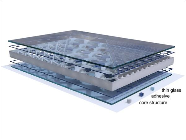
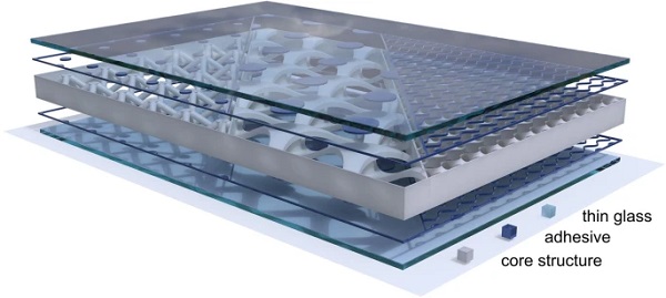
The composite panel (Fig. 1) consists of two cover layers of thin glass that enclose an additively manufactured polymer core. Both components are bonded by an adhesive. The aim of this construction is to distribute the loads as efficiently as possible over the entire cross-section. Bending moments generate normal stresses in the cover layers. Transverse forces lead to shear stresses in the core and in the adhesive joint.
Cover layer
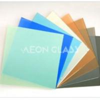
The outer layer of the sandwich construction consists of thin glass. In principle, soda lime silicate glass will be used. Due to the targeted thicknesses of < 2 mm, thermal tempering processes reach their current technical limits. If higher strengths are required due to the design (e.g. cold-bent curved panels) or use, chemically strengthened aluminosilicate glass can be considered as particularly suitable [12]. The function of light transmission and protection against environmental influences will be complemented by the favorable mechanical properties such as a good scratch resistance and a relatively high Young's modulus compared to the other used materials in the composite. Since the available sizes of chemically tempered thin glass are limited, fully tempered soda-lime silica glass sheets with a thickness of 3 mm are here used for the construction of the first large-format prototype.
Core structure
The core structure is considered to be the form-giving part of the composite panel. Almost all properties can be influenced by it. It is also the focus of the digital fabrication process due to its additive manufacturing method. Thermoplastics are processed by fused deposition modeling. This offers the possibility of using a large number of different polymers for specific applications. The topology of the core element can be developed according to its function through different main focus. For this purpose, the form finding can be divided into the following four design categories: structural design, functional design, aesthetic design and manufacturing design. Each of these categories may have different objectives, which may result in different topologies.
In preliminary investigations, some core structures were already examined for their structural design suitability [11]. The triple-periodic minimal surface of the Gyroid core pattern turned out to be particularly efficient from a mechanical point of view. This was able to achieve a high mechanical resistance to deflection with comparably little material use. In addition to this cell-like basic structures, which are duplicated over the surface area, the topology can also be generated by other form finding methods. Stress line generation is a possible approach for optimizing stiffness while keeping weight as low as possible [13]. Nevertheless, the honeycomb core pattern, which is widely used for sandwich structures, is used as a starting point for the development of the production line. This basic shape brings rapid progress in manufacturing, especially through simple tool path programming. Its properties in composite panels have been extensively investigated [14,15,16] and the appearance can be changed in a variety of ways through the use of parameterization and can also be used for initial optimization concepts.
When selecting the polymer, a wide range of thermoplastic polymers can be considered with the extrusion process used. Initial preliminary investigations of small-format materials have already reduced the number of polymers that are considered suitable for use in a façade [11]. Polycarbonate (PC) is promising because of its heat and UV stability as well as its high stiffness. Due to the additional technical and monetary effort involved in processing PC, glycol-modified polyethylene terephthalate (PETG) is being used for the production of the first prototypes. This is particularly straightforward to process at relatively low temperatures and bears a lower risk of thermal stresses and distortion in the component. The prototypes presented here are made from a post-recycled PETG called PIPG. The material is processed in the form of pellets with a glass fibre content of 20% after pre-drying at 60 °C for at least 4 h [17].
Adhesive
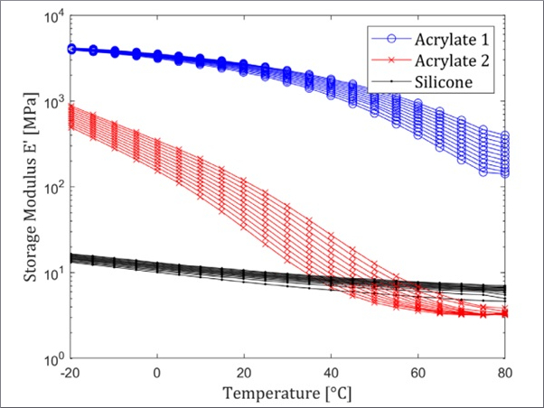
The adhesive provides a permanent bond between the polymer core structure and the thin glass cover layer. When the composite panel is exposed to bending loads, the adhesive joint is under shear stress. Therefore, stiffer adhesives are advantageous and deflections can be reduced. In connection with the transparent material glass, transparent adhesives are also favorable to ensure a high visual quality. Another important factor in the choice of the adhesive is processability and integration into the automated production flow. Here, UV-curing adhesives with flexible curing times can significantly simplify the positioning of the cover layers. Based on preliminary tests, a selection of adhesives has already been tested for their suitability for thin glass composite panels [18]. The UV-curing acrylate Loctite® AA 3345™ [19] proved to be particularly suitable and is used in the following process.
Prototype fabrication process
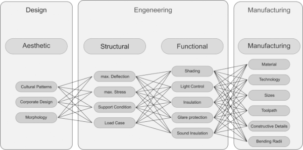
In order to take advantage of the possibilities of additive manufacturing and the flexibility of thin glass, the entire process is aimed to function digitally and parametric. Grasshopper is used as a visual programming interface to avoid interfaces between different programs. All disciplines (design, engineering and manufacturing) will support and complement each other in one file and provide direct feedback to the operator. At this point of the research, the workflow is still in development and follows the diagram depicted in Fig. 2. Different objectives can be summarised inside the disciplines as categories.
While a user-oriented design and the automation of the manufacturing preparation are already used for the production of the sandwich panel in this paper, the integration and validation of individual engineering tools is not yet fully implemented. Starting with the parametric design of the façade geometry, the outer building envelope can be designed on a macro (façade) and meso (façade panel) level. In the second step, an engineering feedback loop is intended to estimate the safety and serviceability as well as the feasibility of manufacturing of the façade. Finally, the resulting panels are prepared for digital fabrication. The program processes the developed core structures in machine readable G-Code and prepares the additive manufacturing, subtractive post-processing and adhesive joining with glass.
Design (CAD)
The design process is considered on two different levels. In addition to the macroscopic shape of the façade, which influences the geometry of each composite panel, the core topology itself can also be designed on a meso level. By means of a parametric façade model, the shape and appearance can be influenced with the sliders shown in Fig. 3 using an exemplary façade section. In this way, the total surface consists of a user-definable, scalable surface, which can be deformed by a point attractor and changed by specifying the minimum and maximum extent of deformation. This ensures a high degree of flexibility in the design of the building envelope. However, this freedom is restricted by technical and manufacturing constraints, which take effect through algorithms in the engineering part later on.
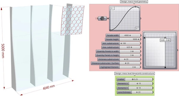
In addition to the height and width of the overall façade, the subdivision of the façade panels is also defined. When it comes to the individual façade panels, these can be defined more precisely at the meso level. The topology of the core structure itself as well as the glass thickness can be influenced. Both of these variables, together with the dimensions of the panel, have an important link to the mechanical simulation in the engineering section. The entire design and engineering on the macro and meso level can be performed with a perspective of optimisation in the four categories of structural, functional, aesthetic and manufacturing design. The user can develop the overall appearance as well as the performance of the building envelope by defining priorities in these fields.
Engineering (CAE)
The design is supported by the engineering part with the help of a feedback loop. For this purpose, target and boundary conditions are defined within the optimisation categories shown in Fig. 2. These provide a corridor of what is technically feasible, building physics reasonable and safe from an engineering point of view, which has a significant influence on the design. This is the starting point for a wide range of tools that can be integrated directly into Grasshopper. With further research, Mechanical properties can be estimated by finite element analysis (FEA) or even analytical calculations.
Also, Solar radiation studies, sightline analyses, sunlight-hours modelling can estimate the building physics effect of the composite panel. It is important not to limit the speed, efficiency and flexibility of the design process too much. Therefore, the results generated here are developed as an additional orientation and support to the design process and do not replace the detailed analysis and proof at the end of the design process. This strategic design forms the basis for further research in the individual categories to provide validated results. For example, so far only little is known about the mechanical behavior of a composite panel under different loading and support conditions.
Manufacturing (CAM)
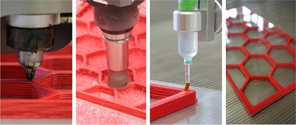
After design and engineering have been completed, the model is prepared for digital manufacturing. The manufacturing process is divided into four substages (Fig. 4). First, the core structure is additively manufactured by means of a large-scale robotic 3D-printing setup. Then the surface is milled, using the same robotic system, to improve the surface quality needed for high-quality adhesive bonding. After milling, the adhesive is applied along the core structure by a specially devised dispensing system mounted on the same robotic system as used for the printing and milling processes. Finally, the glass is positioned and placed down before the adhesive joint is cured by UV-light.
Additive manufacturing of the core
For additive manufacturing, the defined topology of the core structure must be translated into numerical control machine language (GCode). For homogeneous and high-quality results, the aim is that each layer can be printed without the extruder nozzle coming off. This prevents undesired over-extrusion at the start and end points of the travel move. Therefore, a continuous toolpath generation script is written for the used honeycomb pattern. This creates a parametric, continuous polyline with the same start and end point which adapts to the selected panel size, number and size of honeycomb cells according to the design. Furthermore, parameters such as line width and height can be specified before the line is stacked by the number of layers to reach the desired height of the core structure. The next step of the script is to write the G-Code commands.
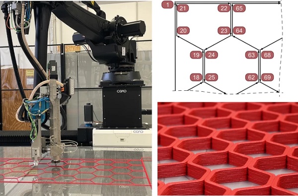
This is done by writing the coordinates of each point in a line with further machine-specific information such as other relevant axes for positioning and controlling the extrusion quantity. The generated G-Code can then be transferred to the production machine. In this case, a Comau NJ165 industrial robot arm on a linear track is used to handle CEAD's E25 extruder according to the G-Code (Fig. 5). For the first prototypes, a post-industrial PETG with a glass fibre content of 20% is used. With regard to mechanical tests, a size close to a construction industry size is aimed for, therefore the core element is produced in the size of 1983 × 876 mm with 6 × 4 honeycomb cells. The nozzle extrudes the Material at 265° C to a printed line with 6 mm width and 2 mm height on an 80° C preheated glass surface.
Milling of the core
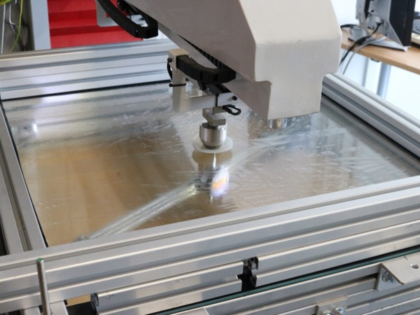
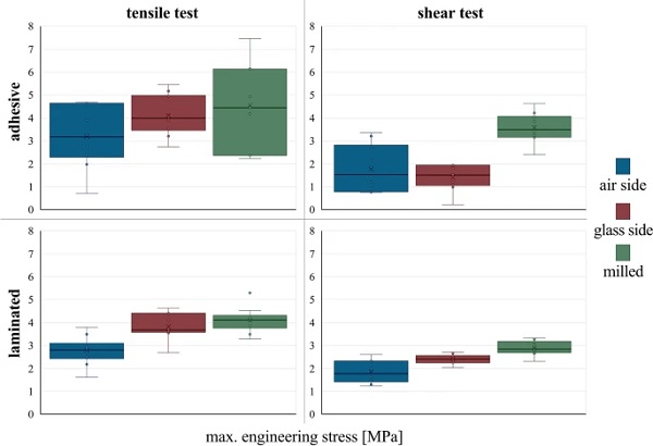
Preliminary tests have already shown differences in the adhesive bonding strength between the adhesive and the 3D-printed polymer depending on its surface properties. For this purpose, additively manufactured test specimens were bonded by an adhesive or were laminated to glass and loaded in tension or shear. A significant increase in strength was found when the polymer surface was mechanically pretreated by milling (Fig. 6). Furthermore, it improves the planarity of the core and prevents defects caused by over extrusion. The UV-curing acrylate LOCTITE® AA 3345™ [19] used here appeared to be sensitive to the processing conditions.
This leads to generally higher standard deviations for adhesively bonded test specimens. After additive manufacturing, the core structure is milled down by a copy mill. The G-Code required for this is automatically generated according to the tool path already created for the 3D-printing process. It is necessary to print the core structure a little higher than the core height intended. In this example, the 18 mm thick core structure was milled down to 14 mm.
Application of Adhesive
This part of the manufacturing process represents a significant challenge for full automation. The application of the adhesive requires a high degree of accuracy and precision of the machine. A pneumatic dispensing system is used to apply the adhesive along the core structure. This is guided by the robot over the milled surface according to the already defined tool path. Instead of conventional dosing tips, the application with a brush tip turned out to be particularly favourable. This leads to an even dosing of the volume for low viscosity adhesives. The amount is defined by the pressure applied in the system as well as the speed of the robot. For higher precision and a high-quality adhesive bond, low movement speeds between 200 and 800 mm/min are preferred.
At an applied pressure of 0.3 to 0.6 mbar, the acrylate used with a mean viscosity of 1500 mPa*s was applied to the 6 mm wide polymer core-wall by a dispensing brush with an inner diameter of 0.84 mm and a brush width of 5 mm. The adhesive then spreads on the substrate surface and forms a 1 mm thin coating due to the surface tension. An exact definition of the adhesive thickness could not yet be implemented automatically. The duration of the process is a relevant criterion for the selection of the adhesive. The core structure produced here has a track length of 26 m, which results in an application time of 30 to 60 min.
Assembly and curing
After the adhesive has been applied, the pane is placed in position. Since thin glass already deforms strongly under its own weight because of the low material thickness, the pane must be held as flat as possible when it is placed. For this purpose, a pneumatic glass suction cup with punctually distributed suction cups is used. It is placed over the component with the help of a crane, and potentially in the future directly with the robot. The glass pane is placed parallel to the surface of the core structure on the adhesive layer. The pressure on it, resulting from the low weight is increased by another glass pane (4 to 6 mm thick).
The result should be a complete moistening of the glass surface along the core structure, which can be judged by an initial visual inspection of clear colour differences. The application process can also have a sensitive influence on the quality of the resulting adhesive joint. Once applied, the pane must not be repositioned, as this will result in visible adhesive residues on the glass and imperfections in the actual adhesive layer. The adhesive is finally cured by UV radiation with a wavelength of 365 nm. For this purpose, a UV lamp with a power density of 6 mW/cm2 is held incrementally over the entire adhesive surface for 60 s.
Mechanical testing
The here investigated concept of a lightweight and customisable thin glass composite panel with an additively manufactured polymer core, is intended to be used in future façades. Therefore, the composite panel should comply with the applicable standards and meet serviceability limit state (SLS), ultimate limit state (ULS) and safety requirements. The composite panel should thus be sufficiently safe, strong and stiff to carry loads (e.g. surface loads) without showing collapse or too large deformations. To investigate the mechanical response of the previously produced thin glass composite panel, as presented in “Mechanical testing” section, it has been subjected to a wind load test, as described in the following subsections.
Physical test setup
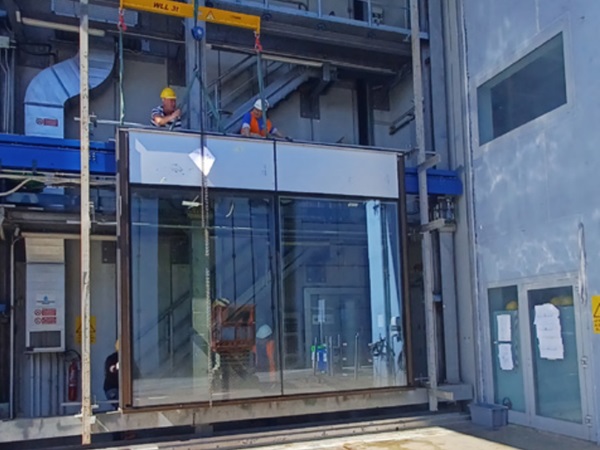
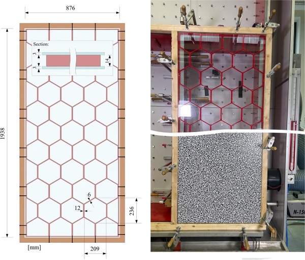
The objective of the physical test is to investigate the mechanical behaviour of the composite façade panel under wind load. For this purpose, a composite panel made of 3 mm fully tempered glass outer sheets and a 14 mm thick additively manufactured core structure made of PIPG-GF20 is prepared using the Loctite AA 3345 adhesive from Henkel in the above described method (Fig. 7 left). The composite panel is then mounted to a wooden support frame using metal screws that are screwed through the wooden frame into the side of the core structure. The 30 screws are placed along the perimeter of the panel (see black lines in Fig. 7 left) and are intended to reproduce as accurately as possible a linear support condition along the perimeter.
The test frame is subsequently installed airtight in a façade test wall, which builds up wind pressure or wind suction behind the composite panel (Fig. 7, top right). A Digital Correlation System (DIC) is used for data recording. For this purpose, the outer glass pane of the composite panel is covered with a thin and elastic sheet that has been printed with a Perlin Noise pattern (Fig. 7, bottom right). The DIC records the relative position of all measuring points over the entire glass surface using two cameras. Two images per second are recorded and used for evaluation. The pressure in the chamber enclosed by the composite panel is increased by a fan in 1000 Pa steps to a maximum of 4000 Pa, whereby each load level is maintained for 10 s.
Numerical simulation
The physical setup of the experiment is also represented by a numerical model with the same geometric dimensions. The numerical program Ansys Mechanical is used for this purpose. The geometry is meshed using SOLID 185 hexahedral elements with an edge length of 20 mm for the glass panes and SOLID 187 tetrahedral elements with an edge length of 3 mm for the core structure. To simplify the simulation at this stage of the research, the acrylate used is here assumed to be idealised stiff and thin and is defined as a rigid connection between glass and core.
The composite panel is fixed in a line around the outside of the core and one glass pane is loaded with a surface load of 4000 Pa pressure. While the simulation takes geometrical non-linearities into account, only linear material models have been used at this stage of the research. While this is a valid assumption for the linear-elastic response of glass (with E = 70 000 MPa), the adopted linear stiffness of E = 8245 MPa according to the manufacturers datasheet [17] of the (visco-elastic) polymer core material must be critically considered in the current analysis and will be investigated in future research.
Results and discussion
The here presented evaluation of the results is focused on the deformation under maximum wind pressure load up to 4000 Pa (=ˆ4kN/m2). For this purpose, the image recorded by the DIC is compared with the results of the numerical simulation (FEA) (Fig. 8, bottom right). While an idealised total deformation of 0 mm with "perfectly" linear support in the edge area (i.e. the perimeter of the panel) is calculated in the FEA, the physical displacement of the edge area must be taken into account in the evaluation of the DIC. This results from tolerances in the mounting as well as a deformation of the test frame and its sealing. For a comparison, the average displacement of the edge area (white dotted line in Fig. 8) is subtracted from the maximum displacement in the centre of the panel. The displacements as determined by DIC and FEA are compared in Table 1 and displayed as graphs in the left top corner of Fig. 8.
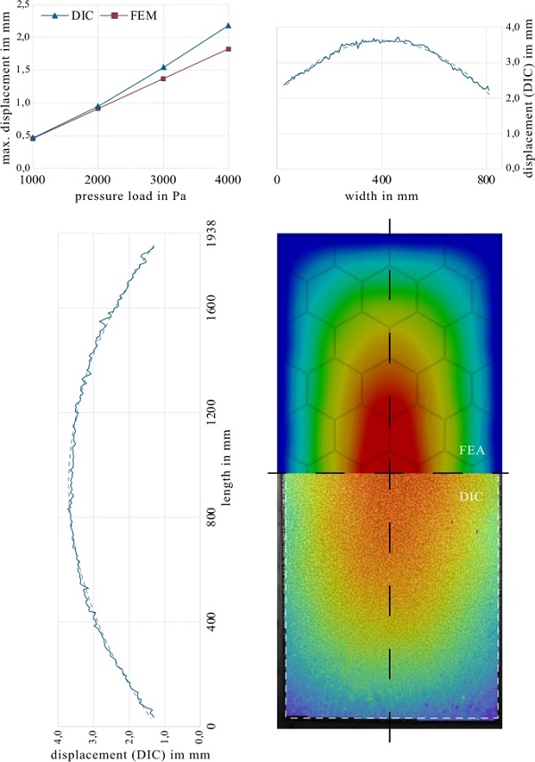
Table 1 Comparison of results between DIC and FEA - Full size table
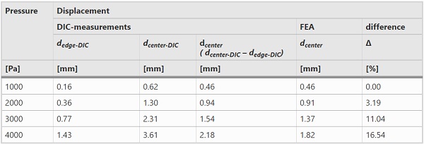
The four applied load levels of the experimental model are used as reference points for the evaluation and are also assessed in the FEA. The maximum centre displacement on the unloaded of the composite panel was determined by DIC-measurements at 2.18 mm at a load level of 4000 Pa. While the displacement of the FEA at lower loads (up to 2000 Pa) can still reproduce the experimental values fairly accurately, the non-linear increase in deformation at higher loads is not calculated accurately.
However, the study already illustrates that the composite panel is capable of handling extreme wind loads. The high stiffness of the lightweight panel can be particularly highlighted. With an analytical calculation based to the linear plate theory according to Kirchhoff [20], the deformation of 2.18 mm at 4000 Pa corresponds to the deformation of a monolithic 12 mm glass pane under the same boundary conditions. The thickness of the (production-energy intensive) glass can therefore be reduced in this composite panel to 2 × 3 mm glass, which results in a 50% material saving. This reduction in the total weight of the panel leads to further advantages in assembly. While the 30 kg composite panel can easily be handled by two people, technical support is required to safely handle a conventional 50 kg glass pane. For an accurate representation of the mechanical behaviour, a more detailed numerical model is necessary in future research. The FEA can be further improved by more extensive non-linear material models of the polymer and modelling of the adhesive joint.
Summary
The development and improvement of digital processes plays a key role in the construction industry to improve both economic and environmental performance. In addition, the use of thin glass in façades promises potential savings in energy and resources and opens up new opportunities in architecture. However, due to the low thickness of the glass, new structural solutions are necessary to sufficiently stiffen the glass. Therefore, the research presented in this paper investigated the concept of a composite panel made of thin glass and an adhesively bonded stiffening 3D-printed polymer core structure. The entire manufacturing process, from design to production has been digitised and automated. A file to factory workflow was developed with the help of Grasshopper to enable the use of the thin glass composite panels in future façades.
The production of a first prototype already showed the feasibility and challenges of the robot-aided production. While additive and subtractive manufacturing could already be integrated very well, especially the fully automated adhesive application and assembly represents more challenges that need to be addressed in future research. By means of preliminary mechanical testing and related exploratory FE simulation, it is shown that the lightweight thin glass composite panel provides sufficient bending stiffness for its intended application in facades, even under extreme wind load conditions. Ongoing research by the authors will further investigate the potential and demonstrate the performance of digitally manufactured thin glass composite panels for façade applications.
Data availability
Data on which this paper is based is available from the authors upon reasonable request.
References
Acknowledgements
The authors would like to thank all supporters in relation to this research work. Acknowledgements go to the EFRE funding programme of the SAB, financed from European Union funds, for providing financial resources for the acquisition of the robot arm with extruder and milling unit, through grant nr. 100537005. Also AiF-ZIM is acknowledged for funding the Glasfur3D research project (fund nr. ZF4123725WZ9) in collaboration with Glaswerkstätten Glas Ahne, which provided this research work with significant support. Finally, the Friedrich-Siemens-Laboratorium and their staff, especially Felix Hegewald as well as student-assistant Jonathan Holzherr, are acknowledged for the technical support and implementation of manufacturing and physical tests as the background for this paper.
Funding
Open Access funding enabled and organized by Projekt DEAL.
Author information
Authors and Affiliations
- Institute of Building Construction, Faculty of Civil Engineering, Technische Universität Dresden, Dresden, Germany - Daniel Pfarr & Christian Louter
- Structural Design & Building Engineering, Faculty of Civil Engineering & Geosciences, Delft University of Technology, Delft, The Netherlands - Christian Louter
Corresponding author
Correspondence to Daniel Pfarr.