
Authors: Dhananjay Joshi and James E. Webb
Source: International Journal of Structural Glass and Advanced Materials Research, Volume 3, Science Publications
DOI: https://doi.org/10.3844/sgamrsp.2019.87.97
Abstract
This study provides important design guidance to the Photovoltaic (PV) solar panel development efforts using the finite element based computations of the PV module under the mechanical loadings. We consider specialty thin glass (Corning Eagle XG®) as superstrate of the PV module, while a standard tempered Soda-Lime-Silica Glass (SLG) is considered as bottom support. The reliability calculations for the module were performed based on the stress magnitudes obtained from the FEA computations. The PV solar panel considered in this study are supported by C-chanel rails that run along the longitudinal direction. The optimum values for the C-chanel rail support location and height were determined using FEA driven reliability calculations.
A methodology involving back calculation of the limiting stresses from the reliability constraints is briefly discussed, that can save the time consuming FEA iterations and tedious post processing of FEA results thereafter to calculate reliability. Analysis shows that the best rail position is between 17% to 20% of the module width (L) from the edge. The channel located at close to L/5 from the free edges was found to give mechanical reliability of 99%. Rail height greater than or equal to 23.5 mm can be used to achieve 95% reliability for the heavy snow load test. Lower modulus encapsulants such as silicone decrease the stress on top glass Eagle EG (EXG) and increase the stress on SLG (bottom glass) to a bit over the temper stress level. The butyl perimeter seal has a minimal impact on glass stress levels.
Introduction
Solar power can be employed to meet the growing energy demand and reduce the carbon foot print. Solar power utilizes either direct (Photovoltaic (PV) cells) or indirect (lens/mirror tracking) method to convert the sunlight energy into electricity (Chu and Meisen, 2011). In the direct method, typically, PV cells are sandwiched between two glass substrates and the sandwich panel is installed and positioned towards sunlight. The PV panel is subjected to rigorous loading cases designed to predict the mechanical reliability before it can be approved for a commercial use. International Electrotechnical Commission (IEC 61646 Standard, 2008) lay down requirements for the design qualification and approvals for terrestrial PV modules that can be used in snow, wind and hail impact environments. The purpose of this study is to provide module design guidelines using FEA and mechanical reliability calculations to achieve better life expectancy of the glass components used in the module under wind and snow loadings. Experimental evaluation of the various quantities is planned in the future.
Previous analysis (Webb et al., 2009) of the PV module showed that, the specialty ultra-thin Eagle XG® 0.7 mm thick glass had no failures under a standard 25 mm ice ball hail test. It was shown via finite element modeling that, the support structure configuration is more important than glass thickness for stresses developed in glass due to wind and snow loading (Webb et al., 2009). It was also found that the back rails (C-Chanel) support structure improves the reliability of the module as compared to frame support structure (Webb et al., 2009). The stress analysis of Photovoltaic (PV) laminates have been considered in literature before. Schulze et al. (2012) analyzed such structure considering transverse shear of polymeric core (encapsulant). Naumenko and Eremyeyv (2014) derived close form analytical solutions for laminated plates with soft core.
Others (Paggi et al., 2011; Ojo and Paggi, 2016) considered thermomechanical and visco-elastic models to analyze the PV laminates. Galuppi and Royer-Carfagni (2012) provided an elegant analytical solution to the laminated beams with viscoelastic interlayer and showed that stress and deflection results could differ as a consequence of ignoring the viscoelastic effects. In another study (Galuppi and Royer-Carfagni, 2013), authors provided practical design rules to account for superposition of applied loads in sandwich structures. As far as the practical analysis of PV modules subjected to the mechanical loadings as per IEC protocol is considered, the literature lacks sufficient information of the overall structural response of thin-glass laminates having optimized support structures. The current study aims to address the reliability of thin-glass PV module laminates having support structure that are subjected to IEC testing protocols.
In the light of a support structure having two rails of C-shaped channel running through the long side of panel, it is necessary to evaluate the stress in superstrate glass and overall reliability of glass components within the panel. The new FE model for the entire PV stack was developed in ABAQUS® and tested for simulated wind and snow loadings as per IEC 61646 Standard (2008). It is found that the C-channel height and spacing can greatly affect the stresses and deformations of thin glass (EXG) and Soda-Lime-Silicate (SLG) glass. Based on sensitivity studies, recommendations are made for Cchannel spacing and height. Other sensitivity studies done included the influence of elastic modulus of an encapsulant, thermal loadings etc.
Modeling Approach
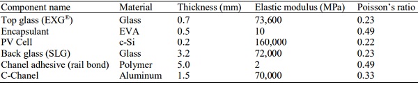
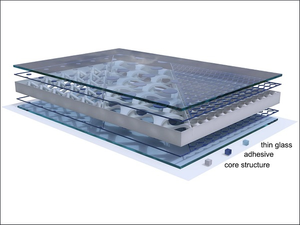
The geometry considered for the panel is 1 m by 2m wide that is supported by two the C-channel about the same length as longer side of panel as shown in Fig. 1 below. The PV module is idealized to a stack having a superstrate of 0.7 mm EXG® glass, Crystalline Silica (cSi) wafer (0.2mm) sandwiched between EVA encapsulant (0.5mm) and a substrate of Soda Lime Glass (3.2mm).
The material property of each of the layers is given in the Table 1. The mechanical properties for the EXG, SLG glass and encapsulant (interlayers) were taken from Reference (Webb et al., 2009). The EVA and adhesive layer were modeled as elastic materials and any time dependence of material properties was ignored for simplicity.
The finite element model was built in ABAQUS® based on geometry (Fig. 1), using a continuum shell elements (SC8R) for the stack components. The stack components were assumed to be perfectly bonded at the interface and no delamination between adjacent layers was modeled. The continuum shell elements (Fig. 3) are different than the regular shell elements in ABAQUS as continuum elements discretize the entire three-dimensional body unlike discretizing the reference surface in case of conventional shell elements. The continuum shell elements allow finite membrane deformations and large rotations and, thus, are suitable for non-linear geometric analysis. These elements also include effects of transverse shear deformation and thickness change (Abaqus® Documentation, © Dassault Systèmes 2015). The rail bond adhesive that connects SLG bottom surface to C-Chanel rail was modeled using continuum solid elements (C3D8RH) due to its low modulus and Poisson’s ratio close to 0.5. C-Chanel rails were modeled using conventional thin shell quadratic elements (S8R).
Loading and Boundary Conditions
Three main loading cases are considered in this study that includes: Forward wind, Heavy snow and Reverse wind. The first two loads are applied on the “sun side” of the panel or on surface “S1” as shown in Fig. 2. The reverse wind load was applied on the “shade side” or surface “S4”. For Forward and Reverse wind load cases, the magnitude of the pressure load used was 2400 Pa, while, for Heavy wind load case, pressure magnitude of 5400 Pa was used (IEC 61646 Standard, 2008.). Test durations for Forward wind are two hours, Reverse wind is three hours and snow load is an hour to achieve the snow load rating. The wind load rating is achieved by replacing the one hour snow load with one hour forward wind load such that the wind load is applied 3 h to each side per IEC-61215 (IEC 61646 Standard, 2008).
The panel is glued to the C-Chanel using adhesive layer. The two C-Chanel are attached to the cross-rails (not shown) at four locations as shown in Fig. 1. The nodes on the C-Chanel are constrained in all DOF’s to simulate the connection.
The important geometric sensitivity parameters in the analysis are Chanel height and relative spacing.
Analysis Procedure
Reliability Approach: The Finite Element Analysis provides with the stress components in the glass when the module is subjected to various load cases discussed earlier. The glass strength is statistical in nature and is typically represented by using the Weibull distribution (Gulati et al., 2002; Ballarini et al., 2016). This study makes use of statistical approach combined with an understanding of how strength changes over time (Webb et al., 2009). This approach considers following factors that influence the survival probability (Webb et al., 2009):
a. Probability factor-that describes the strength distribution
b. Area factor-that describes the difference in strength between a product and (smaller) test sample used in measurements. This factor accounts for fact that a larger strength controlling flaw is more likely to be present in larger parts
c. Fatigue factor-that describes the decrease in strength with increasing time duration under stress
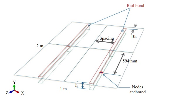
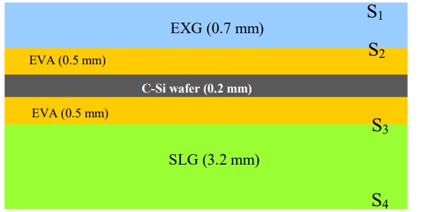
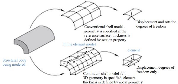
Table 1: PV Stack material properties (Webb et al., 2009)
The Reliability factor “R” can be expressed as (Webb et al., 2009):
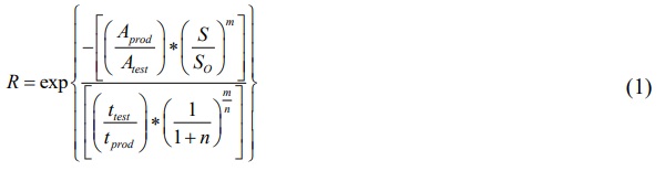
where, A is the stressed area of specimen in strength test or inside module, S is stress in the component, S₀ is the characteristic strength of the glass, m is Weibull modulus, n is fatigue exponent. ‘t’ refers to the time duration. The suffix “prod” stands for actual product conditions and “test” stand for testing conditions. Aprod indicates the stresses area in the module glass that has at least 80% of the peak tensile stress.
For the PV module considered in this study, the reliability is calculated based on individual contribution of reliability parameters from Forward Wind (FW), Heavy Snow (HS) and Reverse Wind (RW) loads at surface (s) and edge (e) of the glass. The overall reliability contribution can be written as a product of reliability of each component:
![]()
As seen from Equation (1), the important contributions toward factor R, comes from the stress magnitude, S and Aprod. Moreover, based on Finite Element Analysis it was found that the reliability for the Heavy Snow load on surface dominates the other terms in Equation (2).
Finite Element Analysis: Finite Element was built using ABAQUS® software as described in the section II. The static structural step with implicit automatic time stepping was used to solve the problem. The mesh convergence study was done to ensure the accuracy of the solution.
Results
Effect of Chanel Location on Stress and Deflection
We report the results for geometric configuration of PV panel shown in Fig. 1 with channel height (h) = 2.5” = 63.5 mm. L is supported width of the panel. The Chanel spacing variations are shown in Fig. 4. Four spacing cases were considered – L/6 = 0.167L, L/5 = 0.2L, 23L/100 = 0.23L, and L/4 = 0.25L.
The corresponding results for the peak principal stress (MPa) at each interfacial surfaces and maximum out-of-plane displacements of the solar panel for each load case and at each surface of the glass are shown in the Fig. 5.
As seen from the figure, Heavy Snow (HS) load is dominant load case as stresses and displacements are higher than the other two load cases. Among the Chanel locations studies, the L/6 = 0.167L has minimal stress magnitude for HS and FW load case. For RW load, the minimal stress magnitudes occur on S1, S2 and S3 at L/4. But, the stresses on S4 increase as the Chanel moves towards each other. The reliability was estimated for the above cases using formulation discussed in section II.B and is plotted in Fig. 6.
The optimal Chanel location was considered to be close to L/5 = 0.2L based on this analysis and this value is used in subsequent analyses below, unless mentioned otherwise.
Effect of Chanel Height on Stress and Deflection
The effect of Chanel height (h) on the stresses in glass was studied in order to make the module more compact. The minimum limit on Chanel height ‘h’ is the height of junction box, which is about 20 mm. Height of Chanel was varied between 20mm-40 mm.
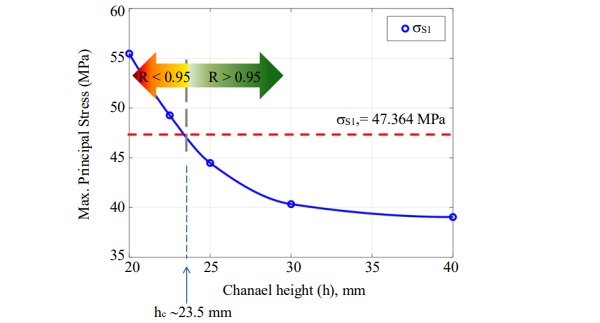
As seen from the Fig. 7, the Max. stresses at surface S1 vary significantly with respect to the Chanel height.
Figure 8 shows the maximum deflection of the panel due to heavy snow load in the region where the support rails are located. As seen, the maximum deflection is less than the Chanel height considered for heavy snow load.
Estimation of Critical (Minimum) Chanel Height
The critical Chanel height was determined based on the approach discussed below:
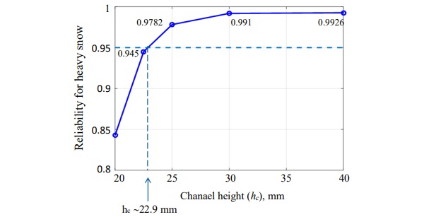
a. Given the reliability estimates should be R≥0.95 and using the Equation 1, the curve can be constructed for R as function of σ (stress) for the given Aprod value at Surface S₁. The estimates of m and n used are 10 and 24 respectively. Atest is area of test specimen, 127 mm² . Characteristic strength of the glass was estimated to be 167 MPa. Aproduct used in Fig. 9 is based on FE calculations and top glass surface (S1) is chosen as it was found to be dominant stress among all surfaces (SLG being a tempered glass). From the R vs. σ curve, find the σS₁′ corresponding to the R value of 0.95
b. Based on Stress vs. h curve, determine the value hc that corresponds to σS₁′.
The Fig. 9 and 10 shows the results based on above procedure.
As an alternative approach, one can directly estimate the hc directly based on the stress available from Fig. 7. This alternative estimate is shown in Fig. 11. Based on two approaches, a conservative estimate of 23.5 was chosen as the critical minimum height such that R≥0.95.
Effect of Elastic Modulus of Encapsulant on Stresses in Glass:
The analysis performed in this study considers elastic material properties. As the material properties of encapsulant layer depend on time and temperature, it was chosen to perform a sensitivity study on elastic modulus of encapsulant layer. The elastic modulus of the encapsulant (EVA) was varied between the value of 0.05-50 MPa (that covers the temperature range from about 120C to -20C (Paggi et al., 2011)) to check the sensitivity to the glass stresses. The Poisson ratio of 0.49 was used.
Chanel Location from Edge
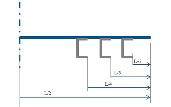
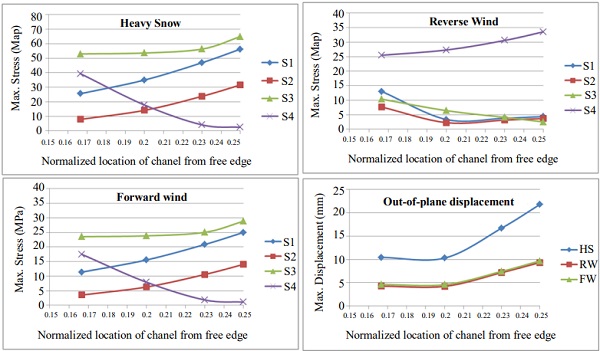
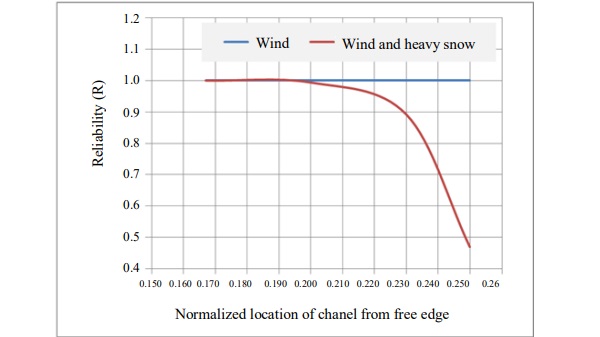
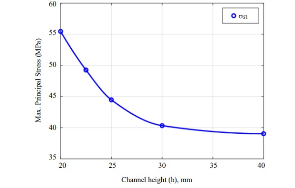
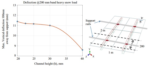
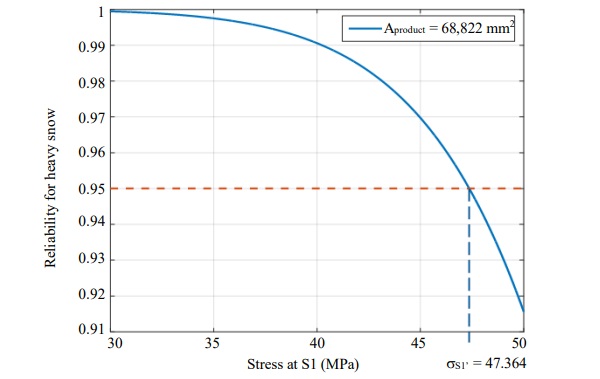
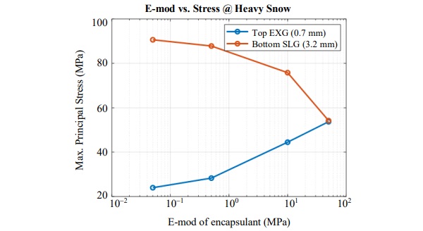
Figure 12 shows the effect of modulus of encapsulant on the magnitude of principal stresses in the EXG and SLG glasses due to heavy snow load.
As seen, the stresses in EXG glass are reduced due to use of less stiff encapsulant, while, the stresses in SLG glass are increased beyond the tempering limit of 70 MPa. For the given encapsulant, the maximum principal stresses in both glasses are within the limits.
Butyl Perimeter Seal
The effect of butyl perimeter seal was investigated by modeling the seal across the perimeter of the panel. The width of the seal was about 8 mm and elastic modulus value at the room temperature was estimated to be between 0.75-0.87 MPa based on DMA at room temperature. The maximum principal stresses in EXG glass were found to be about 28 MPa, while, the stresses in SLG were about 85 MPa, slightly more and slightly less than the stress magnitudes without the perimeter seal respectively.
Thermal Stresses in c-Si Wafer
The analysis of the thermally induced stresses was done to simulate the exposure of the panel to extreme temperatures between -40°C and 90°C. The thermal stresses in the panel are a result of the thermal expansion mismatch of the individual layers.
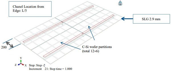
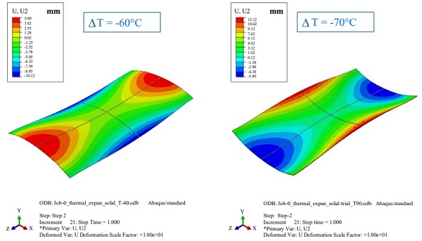
The encapsulant has highest thermal expansion among the other material layers, while, glass and silicone expands the least. Partitions of the c-Si wafer layer was considered as shown in Figure 13.
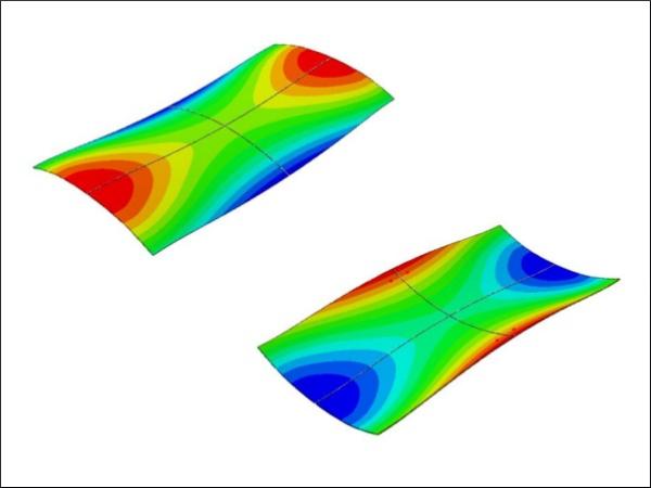
The ΔT (thermal gradient from the room temperature) of -60°C and +70°C was considered to simulate the thermal loads stated above. The maximum out-of-plane deformation of the panel was about 10 mm for ΔT of -60°C, while, it was about 12 mm for ΔT of +70°C. Figure 14 shows the typical deformation contour plots.
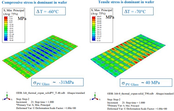
The stresses inside the EXG glass are about -31 MPa due to ΔT of -60°C, while, about +40 MPa for ΔT of +70°C. The stresses in the c-Si wafer follow the similar trend in the magnitude as shown in Fig. 15.
Discussion
In this study, finite element analysis of the PV module was performed considering different aspects of design and loading conditions. As discussed in the results section, the most important contribution to the stresses within glass layers comes from the location and geometry of the supports. It is found that the Chanel located between about L/6 to L/5 from the outer edge would yield optimum stresses and displacements when subjected to snow and wind loads. Similarly, under the compactness condition, the minimum height of the C-Chanel is set to be about 23.5 mm such that the Reliability factor (R) is greater than or equal to 0.95. The numerical sensitivity studies involving the effect of encapsulant modulus (at room temperature) on the glass stresses revealed that the low-modulus encapsulant would lower the stresses in EXG glass, while it would increase the stresses in SLG glass substrate. For the current value of Emod of 10 MPa, the reliability of the module is greater than 0.95. Considering the butyl perimeter seal of width 8 mm along the periphery of the module lowers the stresses in EXG glass (about 28 MPa), but slightly increases the stresses in SLG (85 MPa). The finite element calculations of thermal mismatch of the individual layers within module show that the stresses and deformations of module are within the limits.
Conclusion
This study finds the optimal design parameters of the support structure consisting of two C-Chanel that support the Glass-Glass PV module having thin glass on top and SLG at the bottom. Based on analysis described here, it was found that optimal channel location from free edges is close to L/5 that gives mechanical reliability of 0.99. A methodology for finding the optimum channel height based on the reliability constraints (R≥0.95) is briefly discussed. From compactness point of view, the channel height was estimated to be greater than equal to 23.5 mm that satisfies R≥0.95. Sensitivity of encapsulant E-mod, perimeter seal and thermal loading was performed and it was found that the stresses in glass are within the safe limits. Lower modulus encapsulant such as silicone decreases the stress in the EXG, while increase the stress in SLG to levels above the tempered stress level. The butyl perimeter seal has a minimal impact on stress levels in glass.
Acknowledgement
Authors would like to extend thanks to Dave Wilcox of Corning Inc. for the helpful technical discussions on the topic. This work was supported by the Corning Inc. S&T division.
Author’s Contributions
Dhananjay Joshi: Performed FEA simulations, participated in reliability calculations and discussions, writing of manscript.
James E. Webb: Conceived the project and modeling plan, provided reliablity calculations framework, results discussion and proofing of manscript.
Ethics
This article is original and contains unpublished material. The corresponding author confirms that all of the other authors have read and approved the manuscript and no ethical issues involved.
References
Abaqus® 2016 Documentation, © Dassault Systèmes, 2015.
Ballarini, R., G. Pisano and G. Royer-Carfagni, 2016. The lower bound for glass strength and its interpretation with generalized Weibull statistics for structural applications. J. Eng. Mechanics, 142: 0401-6100. DOI: 10.1061/(ASCE EM.1943-7889.0001151
Chu, Y. and P. Meisen, 2011. Review and comparison of different solar energy technologies. Global Energy Network Institute.
Galuppi, L. and G. Royer-Carfagni, 2012. Laminated beams with viscoelastic interlayer. Int. J. Solids Structures, 49: 2637-2645. DOI: 10.1016/j.ijsolstr.2012.05.028
Galuppi, L. and G. Royer-Carfagni, 2013. The design of laminated glass under time-dependent loading. Int. J. Mechanical Sci., 68: 67-75. DOI: 10.1016/j.ijmecsci.2012.12.019
Gulati, S.T., J.D. Helfinstine, T A. Roe, M.L. Hillman and J.C. Lapp, 2002. 6.2: Biaxial strength of ultrathin AMLCD glass substrates. SID Symposium Digest Technical Papers, 33: 49-51. DOI: 10.1889/1.1830842
IEC 61646 and International Standard, 2008. Thin-film Terrestrial Photovoltaic (PV) modules-Design qualification and type approval. Proceedings of the 2nd (Edn).
Naumenko, K. And V.A. Eremeyev, 2014. A layer-wise theory for laminated glass and photovoltaic panels. Composite Structures, 112: 283-291. DOI: 10.1016/j.compstruct.2014.02.009
Ojo, S.O. and M. Paggi, 2016. A thermo-visco-elastic shear-lag model for the prediction of residual stresses in photovoltaic modules after lamination. Composite Structures, 136: 481-492. DOI: 10.1016/j.compstruct.2015.10.023
Paggi, M., S. Kajari-Schröder U. Eitner, 2011. Thermomechanical deformations in photovoltaic laminates. J. Strain Analysis Eng. Design, 46: 772-782. DOI: 10.1177/0309324711421722
Schulze, S.H., M. Pander, K. Naumenko and H. Altenbach, 2012. Analysis of laminated glass beams for photovoltaic applications. Int. J. Solids Structures, 49: 2027-2036. DOI: 10.1016/j.ijsolstr.2012.03.028
Webb, J.E., D.I. Wilcox, K.L. Wasson S.T. Gulati, 2009. Specialty thin glass for PV modules: Mechanical reliability considerations. Proceedings of the 24th European Photovoltaic Solar Energy Conference, Sep. 21-25, Hamburg, Germany, pp: 3253-3257. DOI: 10.4229/24thEUPVSEC2009-4CO.5.2


Comments
This technology looks promising. Great job!