

The results demonstrate an enlightening change in the order of thermal performance of Foam Spacer Systems and Spacer Tube Systems.
Surely this should be the true basis for exchangeability within BFRC Window Energy Ratings? The question of which is posed by Mark Hickox, Sales Director at Thermoseal Group Limited.
Mark Continues: As a significant distributor in the insulated glass (IG) component supply market and now as a manufacturer of our own range of warm edge spacers, we have been heavily involved in the debates relating to manufacturing standards and how IG components influence Window Energy Ratings (WERs). The main focus which has been well documented in the press is in relation to debates about the exact performance of warm edge spacers – whose is better and by what fractions.
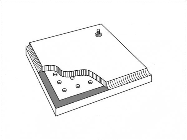
If you look at the figures closely, although spacer bars are proven to affect WERs, it is better to look more closely at thermal transfer at the edge of the unit incorporating all of the edge components including the spacer, desiccant, PIB, and secondary sealant. This is particularly important when you look at single seal systems such as foam spacer which use a minimum sealant depth of 5mm. In this case, there is a greater influence of the sealant which shows a negative effect on the overall thermal rating at the window edge.
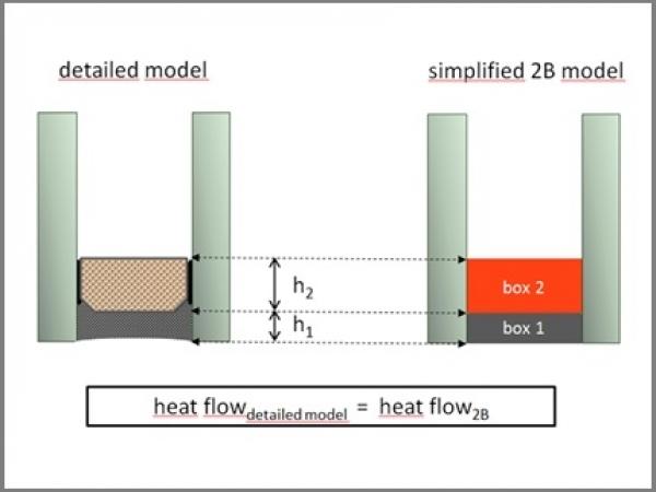
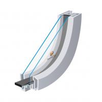
The report includes thermal calculations using the Two-Box-Model. As per the drawings below which have been extracted from the report, the heat flow is calculated including Box 1 (the secondary sealant) and Box 2 (the spacer, PIB and desiccant combination).
It is the column on the far right which shows the resulting figures. As you can see, Thermobar shows the lowest calculated value and hence the best thermal performance across the edge of a glazing unit. Therefore, there should be no question that Thermobar can be substituted for Foam Spacer systems in WER simulation reports without the requirement for re-calculation.
An additional point to reference when considering this report is that a sealant depth of 5mm on single seal foam spacer systems is derived more in terms of what is best in a WER calculation as opposed to what is best in terms of the performance and life of the glazing unit. This is demonstrated when it comes to the reality of meeting the requirements of EN1279 Part 3 standards with such a system.
If proposed changes to documentation go ahead, then by the end of 2013 documented evidence of the performance of foam spacer systems within EN1279 parts 2 and 3 tests at a 5mm sealant depth may have to be provided to notified bodies. In the absence of this evidence a default value using a greater depth of seal may be enforced.
Finally, please also note that these calculations were carried out using the only current published figures (as of the date this was written 18.03.13) relating to the thermal performance of Super Spacer which are from a report carried out by ATI in the USA which is published on the NFRC’s website¹. We await publication of a valid European test report to substantiate these figures. Thermobar and Thermoflex figures are values quoted from reports issued by IFT Rosenheim European Test House.
The report was carried out by Ingrid Quel, Consultant for warm edge and Glass – www.warmedgeconsultant.com.
FULL REPORT:
Thermal performance of insulating glass edge bond
Client: Thermoseal Group Ltd.
Gavin Way, Nexus Point, Holford Broadlands
Birmingham, B6 7AF
Great Britain
Object: Comparison of the thermal performance of insulating glass edge bond, consisting of spacer and secondary sealant, for several types of spacers
Method: Two‐box‐model
To make thermal simulations easier, the two‐box‐model substitutes the detailed geometry of the insulating glass edge bond with two rectangular boxes of the width of the cavity. Box 1 is representing the secondary sealant and box 2 the spacer. The height of box 2 (h2) is identical with the actual height of the spacer [1]. The equivalent thermal conductivity value of box 2, λeq,2B can either be determined by simulation of the detailed model or by means of measurement [2].
.jpg)
To compare the thermal performance of glass edge bond, usually a full thermal simulation according to EN 10077‐2 including window frame and glass is required, which produces comparable Ψ‐values of spacers, if simulated under exactly the same frame conditions.
For quick comparison, a rough and easy assessment can be done by just focusing on the heat flow through the edge bond. The lower the heat flow, the better the thermal performance.
The total heat flow through the edge bond is composed of the heat flow through box 1 and box 2. It is not only depending on the thermal conductivity values λ1 and λeq,2B of the materials, but also on the heights of the two boxes (E.g. twice the height of the same thermal conductivity would double the heat flow). Therefore, because height matters, it would be misleading to simply compare the equivalent thermal conductivity values λeq,2B. Furthermore, it might create wrong conclusions to only look into box 2 and ignore the contribution of box 1, the sealant, to the heat flow.
.jpg)
Click to enlarge.
The two‐dimensional heat flow through a box of a fixed width (cavity) at a defined temperature difference ΔT is proportional to the height of the box and to the thermal conductivity value, i.e. it is proportional to the product h ∙ λ .
.jpg)
Click to enlarge.
Box 1 and 2 were designed to always reach a total height of the edge bond of 10 mm. The width of the boxes (cavity) was 16 mm for all cases.
Result:
.jpg)
* Source: EN ISO 10077‐2:2012
Click to enlarge.
Herrenberg, March 14th, 2013
.jpg)
Ingrid Quel
Consultant for warm edge and glass
Literature:
[1] ift‐Guideline WA‐08engl/1, Thermally improved spacers Part 1 Determination of representative Ψ‐values for profile sections of windows, November 2008, ift Rosenheim, Germany
[2] ift‐Guideline WA‐17engl/1, Thermally improved spacers Part 2 Determination of the equivalent thermal conductivity by means of measurement, February 2013, ift Rosenheim, Germany


.")


.jpg)
.jpg)
.jpg)