This paper was first presented at GPD 2023.
Link to the full GPD 2023 conference book: https://www.gpd.fi/GPD2023_proceedings_book/

Authors:
- Antti Aronen - Glaston Oyj Abp, Finland
- Cenk Kocer - The University of Sydney, School of Physics, Australia
Abstract
Vacuum insulated glazing (VIG) is a glass structure where two glass panes are connected by a hermetic seal over their perimeter, with a vacuum gap between the panes. One case is when this seal is made with solder glass, which is a rigid bridge between the two panes. When a temperature difference over the VIG is established the temperature profile produces bending of the panes and causes deformations, and stresses, in the glass, which affect the strength of glass. In this paper we present a novel approach to formulate an analytical solution for the deformation and stress in a VIG due to a thermo-mechanical load. We apply the analytical solution to three different VIG boundary conditions: free edge, simply supported, and fixed. We include rectangular shaped VIG configurations where the two glass panes can be of different thicknesses. Results are presented for the extreme stress case, where each pane is at uniform temperature over the whole surface.
Introduction
In the EU, the use of high-performance insulating windows has the potential of reducing the total energy consumption of the building sector by 40% by 2050. However, this is only possible if the aged and existing building stock is retrofitted with insulating windows. The Vacuum Insulated Glazing (VIG) is a technology that has the potential to impact the whole building stock in the EU because of its thin profile and low thermal conductance; typically, the VIG would be two panes of 3 mm glass, and a U-value between 0.5-1.0 W m-2 K-1. A primary concern in the application of the VIG design is the ultimate strength of the units with respect to a thermo-mechanical load.
The VIG is constructed from two glass panes that are sealed together at their edges using a hermetic and rigid seal. In typical conditions, the low thermal conductance of the VIG means that the individual panes are at quite different temperatures, and thus, the relative thermal expansion of each pane causes the VIG to bend. The deformation and stress due to a thermal load have been discussed in ISO Standard 19916-3 [1]. In this ISO standard the analytical results of deformations and stresses for freely supported VIG units, under a temperature difference, are outlined. Simko et al. [2] also presented the measurement and numerical simulations of the thermal stresses and deformations in a VIG. The authors showed that measurement results and calculations using the Finite Element Method (FEM) are in good agreement. They also provided an analytical solution, which would provide the means for architects and engineers to simply and quickly determine the impact of VIG design options, with respect to thermo-mechanical loading.
It is clear that measurement and/or FEM simulations of the thermo-mechanical load on a VIG is time consuming and costly. In this study our focus was to determine an analytical solution to the problem of thermo-mechanical loading. In particular we include the outcomes of the free, simply supported, and fixed edge boundary conditions. The theoretical background for the calculation of the stresses and deformations are presented in detail.
Theory of thermal stresses and deformations
Thermal stresses with temperature profile only in one dimension can be presented for the case of a beam and plate. The basic equations are universal, and results can vary with different thermal and external loads and boundary conditions. To present the equations for the stresses and deformations the theory is first presented for a beam and next for a plate.
Thermal stresses in beams
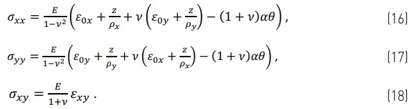
According to Hooke’s law the relation between stresses and strains with thermal strain included is
![]()
Where E is Young’s modulus, α is thermal expansion coefficient, θ is the temperature difference between local temperature T and global reference temperatures Tref (θ=T-Tref). In the Equation (1) the strain εᵪᵪ can be divided in two parts according to Euler-Bernoulli hypothesis: axial strain ε₀ and strain due to curvatures 1/ρ
![]()
In this equation z is the distance in the z-direction from the neutral axis. The bending is simplified only in the z direction because conditions for bending are assumed to be only in the z-direction.
By combining Equations (1) and (2) the stress can be presented as
![]()
When a beam is freely supported the external forces should be zero;
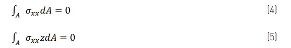
These equilibrium equations lead to the result that Equation (3) can be expressed as
![]()
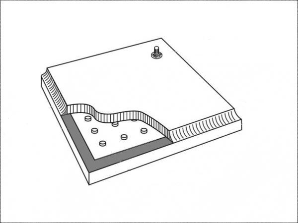
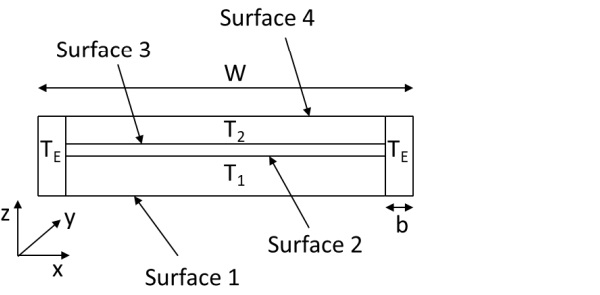
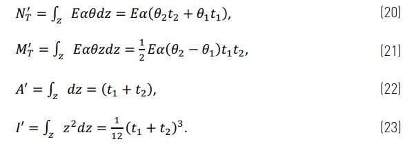
Where thermal forces, cross-section area and moment of inertia, in the case illustrated in Fig. 1 are
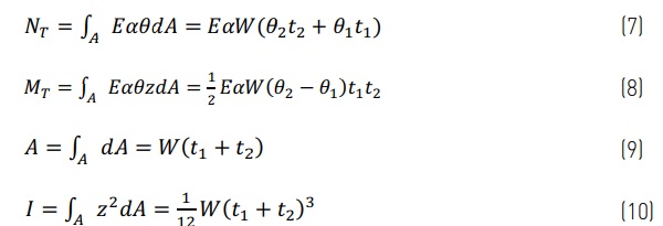
The simplified results of the integrations are calculated for the case where the gap between panes is small compared to the glass thicknesses (g << t₁ and t₂) and the width of the solder glass edge (the edge seal) is small compared to the glass pane width and length (b << W and L).
When there are only external forces acting on the beam then the stress is given as,
![]()
In the case where external forces (such as atmospheric pressure) and thermal load are both act on the VIG pane then the total stress is the combination of Eqs. (6) and (11)
![]()
Thermal stresses in plates
When considering a plate, the equations in the previous section are changed to a two-dimensional form in plane stress state (σzz=0). A plate is defined according to Kirchhoff-Love hypothesis, which means that Eq. (1) is now given as,
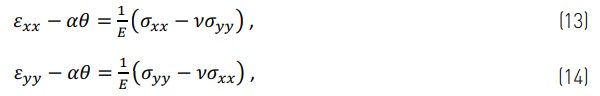
and the shear strain is
![]()
Based on Eqs.(13) to (15) then the stresses are,
When a plate is freely supported over its edges, the external forces should be zero in the x- and y-direction. For a plate, the integration in Eqs. (4) and (5) is calculated only over the glass thickness and in both x- and y-directions. Thus, Eqs. (16) and (17) change to
![]()
Where N'ᴛ, M'ᴛ, A' and I' are similar to Eqs. (7)-(10), but relative to unit length.
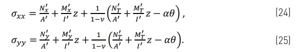
The external forces can be added to the plate as in Eq. (11) of the beam case. Then, if the thermal load and external forces are both involved and Eqs (11) and (19) are combined, as result the stresses are,
For a plate with external forces the shear stress can be calculated as,
![]()
Thermal deformations
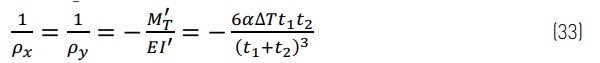
The curvature and deformations are similar between beam and plate cases. The curvature for freely supported VIG is,
![]()
Then deformation in z-direction is,
![]()
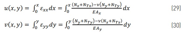
The expansion in the neutral plane in the u and v directions is the integration of the strain over the length.
Thermal stresses in practice
The thermal stresses depend on the magnitude of the thermal load (the temperature difference across the VIG) and the edge of unit boundary conditions (the frame). In the examples given in this study, the thermal load is similar in all cases. That is, when considering the top and bottom parts of a beam, or the plate, are at a uniform temperature and the edge area is at the average temperature of the two parts. In practice the VIG can be supported several different ways depending on the frame installation. In following cases the analytical results are compared to FEM results. In FEM results are for the same geometry as in Fig. 1, but in the analytic results the gap distance g is set to zero as also the width of the solder glass b. Dimensions in the example case are, glass size 350 mm x 500 mm, bottom glass 6 mm thick at 10 °C, and top glass 4 mm thick at 20 °C. In the FEM analysis the gap height is 0.2 mm, and the width of solder glass is 5 mm. The material properties are the same in the analytical and FEM calculations: Young’s modulus E is 70 GPa, Poisson’s ratio ν is 0.22 and the thermal expansion coefficient α is 9·10⁻⁶ 1/°C. N'ᴛ, M'ᴛ, A' and I' can be calculated using Eqs. (20)-(23).
To calculate stresses the boundary conditions form the external forces and moments. Boundary conditions also effect the deformations. For the free case the boundary condition does not create external forces or moments, but for the simply supported and fixed cases the boundary conditions form external moments which are best represented using a trigonometric series. Also, the deformations in the simply supported and fixed cases are presented using the trigonometric series. For all three cases the results are quite different when considering the centre of the unit or the edge region. In the following sections the results are focused on surfaces stresses. In the glass between the top and bottom surfaces the stress changes linearly as in Eqs. (24) and (25).
Freely supported case
For freely supported case the stress conditions depend on the where in the pane the stresses are defined. The stresses at the centre of the pane are based on the plate case and stresses at the edge zone are based on the results from the beam solution.
In the free case, where there is no support at the edge, the external forces and moments are zero N'ₓ=N'ᵧ=M'ₓ=M'y=0. Then stresses can be calculated from Eq. (19), where N'ᴛ, M'ᴛ, A' and I' are from Eqs. (20)-(23). The analytic stress results for each glass surface are calculated below for the case where θ₂=∆T/2, θ₁=-∆T/2, θedge=0 and dimensions are as in Figure 1. The temperature difference ∆T=T₂-T₁. As an example, the stresses calculated on surface 1 are
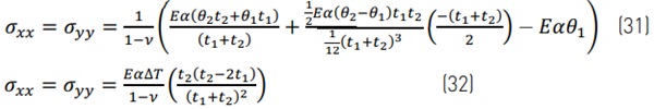
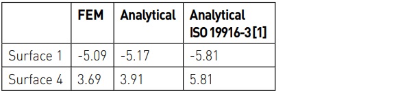
Surfaces 2, 3 and 4 are calculated similarly. Stresses at the edge are calculated based on Fig. 1 for σᵪᵪ according to Eq. (6) and σᵧᵧ=0. All the equations for free case are presented in Table 1.
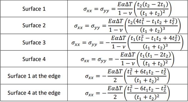
The results for surfaces 1-4 at the centre of the pane are same as presented in ISO 19916-3 [1] in simplified form, where the stresses at the edge are different.
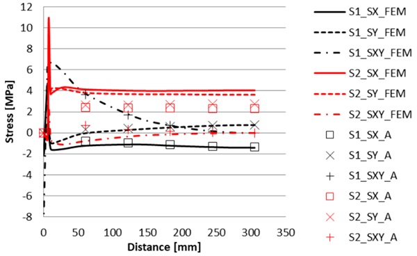
The FEM and analytical results are shown in Fig. 2 along the diagonal line from corner of glass to centre of glass. In plots the FEM results are with lines and analytical results are with dots. Only normal stresses in x- and y-directions are shown, because shear stress σ_xy is zero in analytic results and small in FEM results. Results in Fig. 2 shows that analytical results follow well FEM results except at edge region.
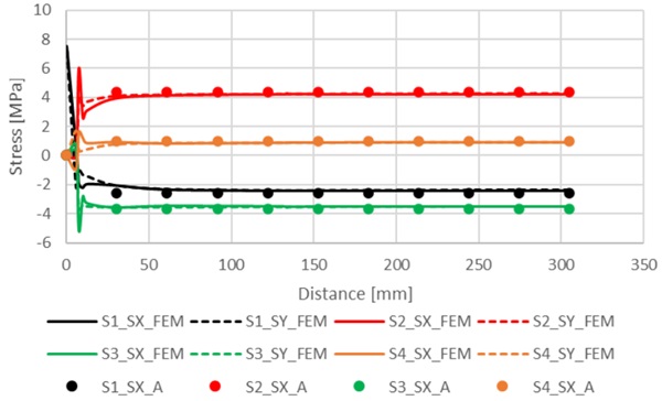
For the edge stresses the results are compared at mid part of the edge. Results from FEM and the analytical cases are shown in Table 2. The edge stress is different comparing stresses at the centre of the glass because the edge temperature is different.
Simply supported case
In the simply supported case compared to the free case, the edge is constrained so that w=0 at the edge, but the edge can still be bent. In this case there is an external moment due to the thermal load and constraints. The equations for the external moments are from [3], pp. 365-367. The external moments and deformations of the pane are presented as a trigonometric series solution. The stresses are solved using Eqs. (24)-(26).
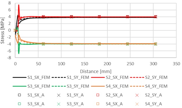
Plots of the results for different surfaces are shown in Figs 3-4. The analytical results at the surfaces 1 and 4 follow well FEM results. However, at the surfaces 2 and 3 there is differences in analytical and FEM results. This is due to differences in model. In FEM model the gap is in model with pillars, but in analytic model there is no gap. This is done to show better how different simplifications affect in results. Effect of the gap is seen in simply supported case, but not in free and fixed cases.

Fixed case
In the fixed case compared to the simply supported case, the edge is fixed so that edge cannot bend. Also, the plate is fixed so that the plate cannot expand or shrink, relative to the edge. This means that N'ₓ=-N'ᴛ/(1-ν) and similarly in y-direction. In this case there is also external moment due to the thermal load and constrains and the equations for external moments are from [3], pp. 371-376.
Results in Fig. 5 shows that in fixed case the stresses in x- and y-direction are same in each separate surface. As seen in Fig. 6 the deformations in fixed case are small and VIG pane stays flat. This means in stresses that stresses in surfaces 1 and 2 are similar and stresses in surfaces 3 and 4 are similar. The results in analytical and FEM calculations are close to each other, except at the edge region. Shear stresses on all surfaces is close to zero at the outside from edge region and not shown in Fig. 5.
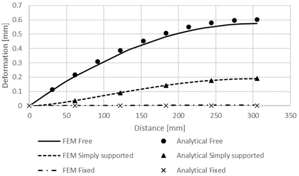
Deformations
The deformations in all three cases are shown in Fig. 6. In these results analytical and FEM results are close to each other. Results also shows that more the VIG pane is fixed at the edge smaller the deformations are.
Conclusions
The results of our analytical solution are presented and compared to FEM simulations, and the agreement is found to be good. In the case of simply supported edges the results differ more because the vacuum gap is not explicitly included in the analytical solution. The case where both panes are at uniform temperature is an extreme case and is possible if the heat transfer coefficient between the glass surfaces and the environment is extremely high; for example, when a VIG is paced in a conductivity instrument for testing. In the usual measurement setup where there is a heat transfer coefficient of heat flow to and from the surfaces, the glass temperature is not uniform and from the centre as you approach the edge of glass the temperature varies exponentially towards the mean edge temperature [4], which affects the edge stress.
In a typical window frame the constraint is somewhere between simply supported and fixed. Sometimes there can also be external normal force involved if the VIG pane is restricted to expand or shrink as in the fixed case. In our analytical method it is also possible to use different boundary conditions in adjacent edges if opposite edges are similar, which will change the external moments and forces.
Our analytical approach is a simple and quick method without the expense of computational methods and measurements. Even though the analytical solution is for only in a few cases, the analytical results give a stress range and easily show the effect of size and thickness changes in the VIG. The analytical method is a simple and speedy way for engineers and architects to understand the design and performance of the VIG product.
Acknowledgements
The authors acknowledge the computing resources supporting this work, provided by the Sydney Informatics Hub, a Core Research Facility of the University of Sydney.
References
[1] ISO 19916-3:2021, Glass in Building — Vacuum Insulating Glass — Part 3: Test Methods for Evaluation of Performance under Temperature Differences, 2021.
[2] Simko, T.M., Fischer-Cripps, A.C., Collins, R.E.: Temperature-Induced Stresses in Vacuum Glazing: Modelling and Experimental Validation. Sol. Energy 63(1), pp.1-21, 1998. https://doi.org/10.1016/S0038-092X(98)00052-8
[3] Noda, N., Hetnarski, R.B., Taginawa, Y., Thermal Stresses, 2nd ed., Taylor & Francis, 2003. https://doi.org/10.1201/9780203735831
[4] Kocer, C., Aronen, A., Collins, R., Asano, O., Ogiso, Y., Measurement of Heat Flow through Vacuum Insulating Glass Part 2: Measurement Area Separated from Glass Sheets with Buffer Plates. Glass Struct Eng 8, pp. 19–39, 2023. https://doi.org/10.1007/s40940-022-00172-2


.")