Article Information
- Digital Object Identifier (DOI): 10.47982/cgc.8.385
- This article is part of the Challenging Glass Conference Proceedings, Volume 8, 2022, Belis, Bos & Louter (Eds.)
- Published by Challenging Glass, on behalf of the author(s), at Stichting OpenAccess Platforms
- This article is licensed under a Creative Commons Attribution 4.0 International License (CC BY 4.0)
- Copyright © 2022 with the author(s)
Authors:
- Alina Joachim - Institute of Building Construction, TU Dresden
- Felix Nicklisch - Institute of Building Construction, TU Dresden
- Alexander Freund - Bollinger + Grohmann Consulting GmbH
- Bernhard Weller - Institute of Building Construction, TU Dresden

Abstract
This paper presents a study on the development of a bonded edge seal for fluid-filled insulating glass units. Such novel façade elements enable multifunctional building envelopes and an improved energy efficiency of buildings. The bonded edge seal of a fluid-filled glazing is highly stressed due to the hydrostatic pressure that acts in addition to typical loads on façades. The permanent exposure to the fluid may also cause severe aging effects. Therefore, the edge seal is designed in such a way that the chemical and physical stress splits on two functional zones. The first functional zone serves as a protective seal and separates the fluid from the second, load-bearing functional zone. The adhesives for both functional zones were selected using an extensive test program.
Once the materials have been selected, the novel façade elements are tested in large scale component tests. The mock-ups are built on a scale of 1:2 compared to the original size of the intended façade elements. Since the study focuses on the performance of the adhesively bonded edge, the edge detail is realized in original size while the glass size is smaller. The glass thickness is modified to achieve rotations in the edge zone that correspond to façade elements in original size. The tests are performed in a test rig for curtain walls, which allows the simultaneous loading of the element by cyclic wind pressure and constant water pressure. The adhesive bond carries all the loads except the deadweight of the glass panes. The test results are compared with the numerical calculations and an estimate of the load-bearing behaviour is made.
1. Introduction
Hardly any other aspect of a building better epitomizes modern architecture than glass façades. Particularly in representative office and administration buildings, maximum transparency and utilization of daylight are desired. Despite the optimized design of high-performance multi-pane insulating glazing units (IGUs), large-scale glazing units are associated with relatively high energy loss. This applies both to the energy input caused by solar radiation in summer and to energy dissipation via thermal conduction, thermal radiation and convection when outside temperatures are low in winter. For this reason, research is constantly being carried out to optimize the façade. The aim is to create multifunctional building envelopes for the construction of ultra-low-energy houses. In recent years, various research projects have been carried out on fluid-filled façade elements. With the help of a fluid the façade elements can be thermally regulated.
The idea of filling the pane cavity with a fluid is based on the high specific heat capacity of water, which amounts around four times that of air. This makes water a very good heat carrier or coolant. This property is not changed by the addition of chemical additives, which are necessary to prevent algae growth. The use of a water-ethylene glycol mixture has proven its worth in several research projects. The fluid mixture can be kept at a constant temperature with only a small amount of energy. In this way, façade elements filled with fluid can contribute to improving indoor temperatures. It is also conceivable to add magnetic particles to the fluid mixture, which react to incident solar radiation and darken the pane.
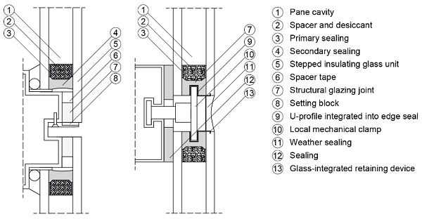
At the same time, aesthetic demands on the building envelope are growing. Structural sealant glazing façades (SSG façades) are in high demand because of their homogeneous surface. Figure 1 shows two cross-sections of SSG façades. The general principle is based on a load-bearing adhesive bond on the backside of either the outer glass pane (stepped insulating glass units) or the inner glass pane (standard insulating glass units). The best aesthetic result is achieved if external clamps are avoided. The result is large glass panels with a minimum of framing.
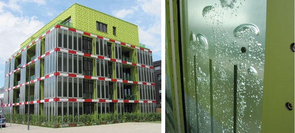
However, if the cavity between the panes is filled with a fluid instead of an air-gas mixture, hydrostatic pressure and the degradation processes caused by the fluid result in high stress on the edge sealant. Therefore, the first pilot applications that resulted from recent research projects have so far always been realized using additional clamps or fasteners. Fig. 2 shows as an example the BIQ algae house, which was built as part of the International Building Exhibition 2006–2013 in Hamburg. The world's first photobioreactor façade is such an application of fluid-filled glazing elements in the façade. Incident solar radiation is used to produce heat and biomass. The façade elements are story-high. The outer clamping frame, which holds the panes together, is clearly visible, Fig. 2 right.
The aim of the current research is to develop a bonded edge seal for fluid-filled insulating glazing that does not require such a frame. The edge seal should then be able to bear the stresses from hydrostatic pressure, wind, and live loads alone, without the need for external clamping. Constant exposure to fluids is another major stress, as the bonded edge seal must remain permanently load-bearing and also leak-proof.
2. Background
2.1. Façade element as example design
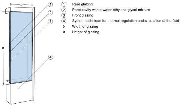
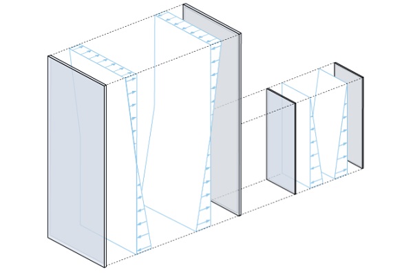
For a stress analysis of fluid-filled façade elements, it is necessary to define geometric and structural boundary conditions. A typical geometry and a practical glass build-up can be derived, for example, from the façade element from the EU research project "InDeWaG – Industrial Development of Water Flow Glazing Systems.” This is a story-high façade element with a height of h = 3000 mm and a width of b = 1350 mm (Fig. 3). The pane cavity is approximately d = 24 mm. It contains a fluid mixture of water and ethylene glycol (mixing ratio 70:30), which is used for heating and cooling. These basic geometry data serve as orientation as a reference for the study approach in this paper.
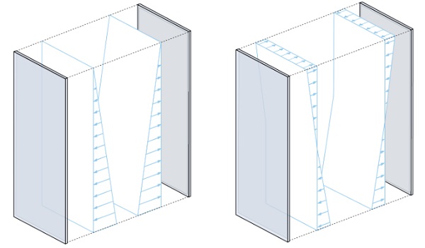
Hydrostatic pressure builds up in the pane cavities as a result of the fluid. This depends on the filling height and results in a triangular load pattern (Fig. 4, left). At a height of h = 3000 mm, a maximum of ph≈ 30 kN/m² results at the base point. The pressure acts perpendicular to the glass surface and results in a tensile stress on the bonded edge seal. Dead loads are not transferred via the adhesive bond. Therefore, no shear stresses occur in the edge seal. To reduce the tensile stress and limit the pane deformation, it is technically possible to generate a vacuum in the façade element (InDeWaG 2019). With a vacuum of pu≈ −15 kN/m² the neutral axis pressure shifts from the upper edge to the center of the element.
The load distribution assumes an antisymmetric shape with a hydrostatic pressure of ph≈ −15 kN/m² at the upper edge and ph≈ 15 kN/m² at the lower edge (Fig. 4, r ight). Even with the help of vacuum technology, the stress is still significantly higher than that of conventional glazing in SG façades. These carry horizontal forces from wind of only approx. 2 kN/m² via the structural bonding. To limit the deformations, a relatively stiff build up of laminated safety glass made of 2 x 10 mm heat-strengthened glass is selected.
2.2. Planned bonded edge seal
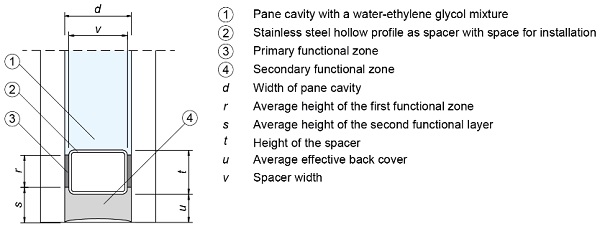
A new type of high-performance edge seal is required to withstand the high mechanical stresses resulting from hydrostatic pressure and also to withstand the expected severe aging stresses resulting from constant contact with the fluid mixture. The design is based on the principle of a conventional edge seal of a gas-filled insulating glass unit. By combining two adhesives, the functions of "sealing" and "load transfer" are thus divided between suitable materials. The zones are referred to below as the first and secondary functional zones. Fig. 5 shows the planned edge seal. The primary functional zone, between the hollow stainless-steel profile, which is used as a spacer, and the glass, is in constant contact with the fluid and responsible for the sealing. The secondary functional zone runs along the unit edge on the outside of the spacer and bears the hydrostatic pressure, the wind and the live loads.
2.3. Adhesive selection and adhesive joint geometry
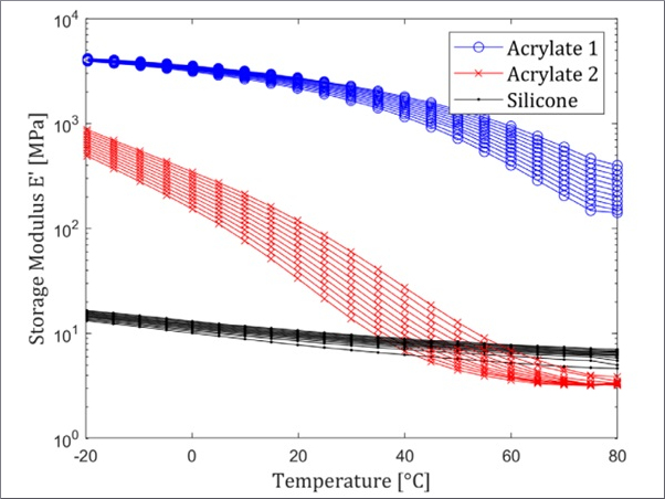
By means of an extensive test program accompanied by numerical calculations, it was possible to select the preferred adhesives for the planned edge seal. For example, the adhesion behavior of the adhesives with and without artificial aging in the water-ethylene glycol mixture was investigated (Joachim 2021) and leak tests were carried out (Joachim 2022). Ultimately, the choice fell on two two-component silicones. For the primary functional zone, the fast-curing Sikasil® AS-785 from Sika was used, which was developed for industrial production. It is characterized by very good adhesion as well as aging resistance. The secondary functional zone is produced with the higher-strength structural glazing silicone Sikasil® SG-550 from Sika. Compared to standard SG silicones, Sikasil® SG-550 allows smaller adhesive joint dimensions due to its high load-bearing capacity.
The accompanying numerical calculations supported the adhesive selection in planning test setups and estimating test results. In addition, it allowed adhesive joint dimensioning after successful adhesive selection. The target pane cavity and thus the thickness of the secondary functional zone was to be approx. d = 24 mm. However, the dimensions of the hollow stainless-steel profile and the thickness of the primary functional zone determined the actual dimension of the pane cavity. The calculations showed that an adhesive layer of Sikasil® AS-785 with a thickness of 4 mm has an optimum ratio between stiffness and deformation capacity. Consequently, a stainless-steel profile with a dimension of v = 15 mm and t = 10 mm was selected as spacer. The adhesive joint height of the primary functional zone is approx. r = 8 mm. This results in a pane cavity and a thickness of the secondary functional zoneof d = 23 mm. The required height of the secondary functional test was calculated to be u = 48 mm.
3. Experimental Investigations
3.1. Test Specimens and manufacturing process
In order to test the planned edge seal, component tests were carried out on mock-ups. Taking into account handling and economy, these should be smaller than the actual façade elements but at the same time represent the structure as realistically as possible. As a result, a 1:2 format was chosen, i.e. panel dimensions of h= 1500 mm and w = 635 mm. This also allows the vacuum technique to be dispensed with, since the mock-ups reach a maximum hydrostatic pressure of ph≈ 15 kN/m2 when filled, thus representing the lower half of the façade element (Figure 6). Since the focus is on the investigation of the bonded edge seal, the edge seal is realized in its original size. In order to keep the loads on the edge seal the same, the glass structure is scaled accordingly so that, as a result of the glass pane deformation, the computed twists in the edge seal correspond to those in the original size. The result is a glass structure of laminated safety glass made of 2 x 5 mm heat-strengthened glass.
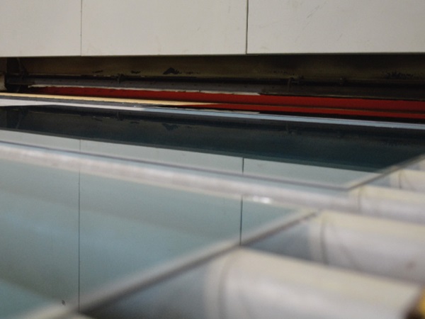
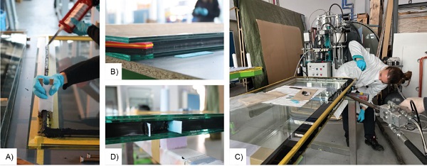
The mock-ups are produced in two steps. In the first step, the Sikasil® AS-785 adhesive (primaryfunctional zone) is applied in bead form to the prefabricated spacer frame. The adhesive is applied from double cartridges. Immediately afterwards, excess adhesive is removed with the aid of a template made of polytetrafluoroethylene (PTFE). This is intended in particular to prevent excess adhesive from overflowing into the pane cavity. Fig. 7a shows both work steps. Subsequently the frame is positioned on the glass pane and pressed. The work step is repeated on the back of the spacer after the adhesive has cured. The dead weight of the second pane is sufficient to generate contact pressure. Care must be taken to ensure that the desired adhesive joint height is maintained. Spacers between the glass panes are used for this purpose (Fig. 7b).
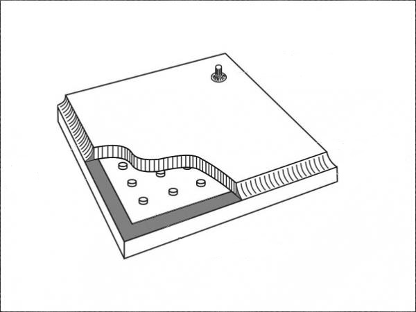
Before proceeding with the application of the secondary functional zone, the adhesive of the primaryfunctional zone is allowed to cure for 24 hours. Afterwards, the remaining cavity between the two glass panes is filled with Sikasil® SG-550 adhesive (secondary functional zone). The adhesive is available exclusively in hobbock form and is processed accordingly with the aid of a plant. Subsequently, the adhesive is removed from the glass edge to achieve a flat surface appearance (Fig. 7c). Two pockets per long glass edge are left free of adhesive. They are later used as an engagement point for mechanical clamps (Fig. 7d).
Two passages are made in the stainless-steel frame on one of the short sides to allow subsequent filling of the mock-ups. A round hollow profile is inserted into these, which serve as recesses in the secondary functional zone.
3.2. Test program
Various loads are conceivable for the façade element, which are listed below. For the design of the wind loads, an example building with dimensions of 40 m x 20 m x 35 m in wind load zone 1, inland, and a load bearing area of 4 m² was assumed (DIN EN 1991-1-4; DIN EN 1991-1-4/NA).
a. Hydrostatic pressure: ph≈ 15 kN/m²
b. Vacuum failure: ph≈ 30 kN/m²
c. Wind pressure: wp≈ 0,76kN/m²
d. Wind suction: ws≈ −1,14 kN/m²
e. Spar load: qh≈ 1 kN/m
f. Impact: m = 50 kg, h = 900 mm
g. Glass breakage: VSG one pane on one side, VSG one pane on both sides.
The load directions are decisive for the selection of the relevant load combinations. Hydrostatic pressure (a and b) acts from the inside to the outside and thus exerts a tensile load on the edge seal. A wind pressure (c) presses from the outside onto the pane and the edge seal with it. A wind suction (d) pulls on the pane from the outside and thus reinforces the tensile load on the bonded edge seal. The linear spar load (e) also presses on the glazing from the outside. Whereas in gas-filled insulating glazing there is coupling of the panes due to the hermetically sealed pane cavity, here the vacuumtechnology compensates for such pressures by means of independent regulation. Accordingly, loads acting against the specified hydrostatic load can be neglected. Nevertheless, impact loads (f) are to be investigated due to the special type of load and are planned together with glass breakage (g) as the conclusion of the component tests.
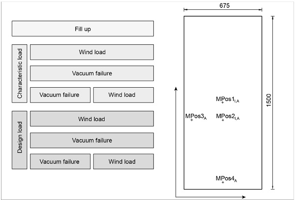
In this paper, the tests under characteristic load and under design load are presented. The entire test program is structured in such a way that the loads are increased in steps. Accordingly, tests are first performed under characteristic load and then under design load. The load is also increased in stages within the tests. First, the mock-ups are filled with fluid (a). Then the wind suction is applied (d). In the next load stage, a vacuum failure is simulated with the aid of an additional water column (b), and finally the wind suction (d) is again applied to the façade element (b) under increased hydrostatic load. There is a 24-hour rest period between each load case or load case combination. Fig. 8 shows the test program.
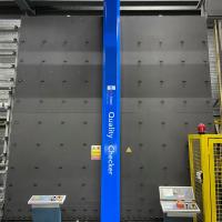
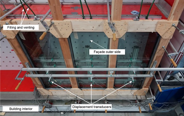
For the tests, the mock-ups are mounted side by side on a test rig for curtain walls. A wooden frame is used for this purpose, which reproduces the substructure on the inside of the façade in the test. The panes are pressed against the frame by means of local mechanical clamps. Apart from the dead weight, which is transferred via an additional cross strut, the glass edges on the outside of the façade are free. During the test, the outer side of the façade faces the interior of the test rig for curtain walls, since wind pressure and wind suction loads are applied from this side. The designations inside and outside therefore refer to the installation in the actual façade and not to the installation condition in the test rig for curtain walls.
The area between the mock-ups and the test rig for curtain walls is sealed airtight to avoid pressure losses. Displacement transducers measure the deformations on the glass surface. Measurements are taken at the center of the pane on the front and rear sides (MPos1: x = 317.5, y = 750), as well as at the point of the mathematically largest deformation (MPos2: x = 317.5, y = 600). On the outside of the façade, the deformation is also measured at the transition between the edge seal and the pane cavity. Both at the height of the maximum deformation (MPos3: x = 65, y = 600) and in the middle of the lower edge (MPos4: x = 317.5, y = 65). Additionally, displacement transducers are placed at the center of the frame posts to estimate the compliance of the system.
At each mock-up, two hoses lead vertically upward and terminate at a height of 1.5 m above the mock-up top edge on a platform in beakers. The hose system can be used to generate additional hydrostatic pressure. One hose is used for filling, the other for venting. Due to their large water surface compared to the hose, the beakers support the constant water column height in the stress case "vacuum failure". Pure water is used for testing purposes. In addition, no difference is expected between the use of pure water and water-ethylene glycol with regard to the load-bearing capacity and deformation behavior of the bonded edge seal.
The wind load applied by the façade test wall is increased in steps of 100 Pa. Each load level is held for one minute before the load is further increased. The target value is held for five minutes.
3.3. Test results
The results are shown as an example for the maximum load level: A combination of wind load and a vacuum failure. For the design load, a partial safety factor of γ = 1.5 is applied to the wind load for short-term loading. The resulting maximum wind load of ws≈ −1.71 kN/m² is rounded up to ws = −1.8 kN/m². In the case of hydrostatic overpressure, an additional safety is omitted, since the load case "vacuum failure" already represents an additional safety.
Fig. 10 shows the time-deformation chart for the above-mentioned load case combination, using the mean value of the three test specimens as an example. The sign definition is based on DIN 18008-2 (Fig. A.1), where all deformations located in the interior direction of the building are defined as positive. In addition, the overall frame deformation is also shown. The gradient of the load increase can be seen well. The glazing is already pre-deformed at the start time due to the fact that the glazing is already filled and the hydrostatic pressure is in effect. At the same time, the mock-ups have already undergone the entire test program. Non-reversible deformations may have occurred in the process.
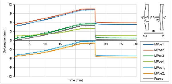
As expected, the deformation in the center of the pane (MPos1) is lower than that at the point with the largest calculated deformation (MPos2). On the inside of the façade, however, the difference shrinks with increasing wind load, but returns to the same extent after the wind load has been relieved. On the inside of the façade, the superposition of hydrostatic pressure and wind suction at MPos1A almost completely restored the initial state (0 mm deformation). The deformation state at the measuring positions at the edge (MPos3 and MPos4) is striking. While MPos4 (edge area short side) shows a very low pre-deformation due to the hydrostatic pressure compared to MPos3 (edge area long side), the deformation at MPos3 increases synchronously to the frame deformation. The deformation at MPos4, on the other hand, is significantly less affected by the wind load.
4. Numerical Investigations
The component tests are simulated numerically and the results validated with the help of the finite element method (FEM). The RFEM software is used. The edge bond is simulated in its individual components of two functional zones and the stainless-steel profile. Instead of implementing 3D volume elements, a rod model is used. In this way, the computing power required can be reduced. The edge bond is divided into regular distances and both functional zones are modeled as individual members. The cross-section of the bar results from the size of the adhesive joint. The spacer made of the stainless-steel hollow profile is composed of surface elements. The primary functional zone is modeled from spring rods. These allow the input of non-linear material properties, which contribute significantly to realistic modeling due to the expected deformations of the functional zone.
The modeling of the shear bond in the laminated safety glass is a particular challenge. This is strongly dependent on temperature and load duration. High temperatures soften the intermediate material and reduce the composite load-bearing behavior. The same applies to long-term loads, as composite films begin to creep over time. A reduction in the composite load-bearing effect increases the sheet deformation. For the calculation, a distinction is usually made between full composite behavior and no composite behavior. For the calculation of a full composite behavior, the pane structure is considered as a monolithic glass structure. For the calculation of deformation without bonding, an ideal equivalent thickness d* is usually assumed, compare (Engelmann et al. 2013). Calculations show that the real composite behavior is between both cases, compare (Krampe et al. 2013). In the FE analysis presented here, the deformations were also calculated for both cases.
However, the approach using the equivalent thickness d* without composite was rejected due to the high deviations. Due to this, a third method assuming a partial composite was investigated. For this purpose, a separate calculation was performed in FE software for structural glass engineering (SJ Mepla), which allows an accurate simulation of the laminated safety glass structure. The PVB film is modelled with a calculated shear modulus of the design load of 0.28 from the literature, which reflects the time and temperature dependence (duration: 1 day; temperature: 20 °C) (Sackmann 2007). The deformation obtained by applying a load can be compared with a monolithic glass pane in the RFEM software and an equivalent thickness d** can be determined that corresponds to the same deformation under the same boundary conditions.
The four mechanical clamps that press the pane against the frame are represented by spring bearings. The spring stiffness is defined according to the flexibility of the wooden frame from the experimental investigations. This is particularly important for the comparability of the wind load case. The support at the lower edge, which serves to absorb the dead weight, is represented by articulated bearings. In addition, two spring bearings are attached to one of the long glass edges, which act in a horizontal direction. The springs have a low rigidity and are only used for the static determination of the system.The hydrostatic pressure is applied to both discs in the form of a triangular area load. A trapezoidal load pattern is applied for the load case "vacuum failure". The wind suction acts as a uniform surface load. In addition to the total deformation and the stress distribution, special points are specified for the calculation (Fig. 11). With the help of these, the numerical results can be compared directly with those from the experimental component tests.
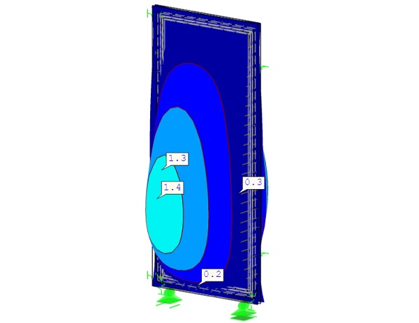
The results are given in the form of the deformation at the four measurement positions on the outside of the façade, Table 1. All four load cases under the design load are listed. The results of the numerical calculation for the assumption of a full composite and the partial composite with the equivalent thickness d** are compared with the actual values from the experimental tests.
Table 1: Comparison of the results from the experimental tests with those from the FEM. The results of the average mock-up under design load are compared.
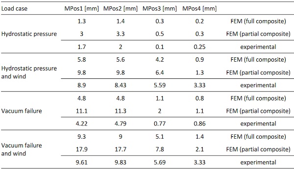
In the hydrostatic pressure load case, the deformations are small. The deformation actually measured is closer to the assumption of a full composite than to the assumption of a partial composite. The model is able to represent the load case well. As expected, the additional wind load applied results in an increased deformation. Here, the results from the FEM assuming a partial composite are closer to the results of the experimental investigation. Only at the measuring point MPos4 (edge area short side) is the deviation higher. Especially since at this measuring position alone the actual deformation is higher than the calculated deformation.
In the load case of vacuum failure, a strong difference between the calculated deformation assuming full composite behavior and assuming partial composite behavior can once again be seen. However, the computed deformation assuming a full compositereproduces the experimental results well. The same applies when a wind load is additionally applied. The calculated deformation under the assumption of a full composite reproduces the experimentally determined deformation well. Only at the measuring position MPos4 does the actual deformation again exceed the calculated values.
5. Discussion
The selected test setup as well as the test execution show reliable results that allow an estimation of the functionality of the edge seal. The mapping of the results using the FEM can also be evaluated as successful. The actual deformations can be found between the calculations assuming full composite behavior and partial composite behavior. To be on the safe side, the model assuming a partial composite should be used for future designs. For the representation of realistic results, for example for further test planning, the calculations assuming a full composite are the better choice. Only the results at measuring position MPos4 should be checked in the calculation. If necessary, the storage conditions at the lower edge of the disk should be redefined.
Measurement errors in the experimental procedure can be largely ruled out at this point. On the one hand, the measuring equipment was checked, and on the other, the two other mock-ups show similar results. With regard to the verification of the load-bearing capacity of the edge seal, the component tests do not allow a reliable statement to be made at the current status, since the test scope with three test specimens is too small for a statistical evaluation. It remains to be discussed whether this can be dispensed with by a validated FE model or whether the tests should be investigated with an increased test scope and higher load levels.
In any case, the numerical calculations provide the possibility to estimate the load capacity of the adhesive bonding. The calculated stress in the secondary functional zone is σ = 0.13 N/mm² for the load combination vacuum failure and wind. The characteristic load is determined here in order to be able to determine the capacity of the adhesive according to the deterministic safety concept in accordance with ETAG 002-1. With a design tensile strength of σD = 0.2 N/mm², which includes all material safety factors, the SG-550 is utilised to 65 %.
6. Summary
The tests presented here hold out great hope that fluid-filled insulating glazing with a frameless, bonded edge seal could become feasible in the future. The newly developed, two-stage edge seal design has proved successful in the experimental tests. The numerical calculations allow a sufficiently accurate prediction of the deformation behavior and the design of further façade elements. In addition to the planned long-term tests on the mock-ups presented here and the failure tests, full-scale experimental investigations are also considered useful. These also allow an evaluation of the test setup presented here and, if successfully verified, could contain the testing effort of future tests without losing reliability.
Acknowledgements
The study results from the research project “fluidIGU” funded within the KLEBTECH network through the Central Innovation Program (ZIM) by the German Federal Ministry for Economic Affairs and Energy (BMWi). Special thanks go to the project partners Bollinger + Grohmann Ingenieure and ADCO Technik GmbH for the good cooperation and technical support.
References
DIN EN 1991-1- 4 :2010-12: Eurocode 1: Einwirkungen auf Tragwerke - Teil 1-4: Allgemeine Einwirkungen - Windlasten; Deutsche Fassung EN 1991-1- 4:2005 + A1:2010 + AC:2010. https://dx.doi.org/10.31030/1625598
DIN EN 1991-1- 4/NA:2010-12: Nationaler Anhang - National festgelegte Parameter - Eurocode 1: Einwirkungen auf Tragwerke - Teil 1-4: Allgemeine Einwirkungen – Windlasten. https://dx.doi.org/10.31030/1723628
DIN EN 1991-1- 1:2010-12: Eurocode 1: Einwirkungen auf Tragwerke - Teil 1-1: Allgemeine Einwirkungen auf Tragwerke -Wichten, Eigengewicht und Nutzlasten im Hochbau; Deutsche Fassung EN 1991-1-1:2002 + AC:2009. https://dx.doi.org/10.31030/1719026
DIN EN 1991-1- 1/NA:2010-12: Nationaler Anhang - National festgelegte Parameter - Eurocode 1: Einwirkungen auf Tragwerke - Teil 1- 1: Allgemeine Einwirkungen auf Tragwerke - Wichten, Eigengewicht und Nutzlasten im Hochbau. https://dx.doi.org/10.31030/1725673
DIN 4103-1 :2015-06: Nichttragende innere Trennwände - Teil 1: Anforderungen und Nachweise. https://dx.doi.org/10.31030/2318743
DIN 18008-4:2013-07: Glas im Bauwesen - Bemessungs- und Konstruktionsregeln - Teil 4: Zusatzanforderungen an absturzsichernde Verglasungen. https://dx.doi.org/10.31030/2006044
Engelmann, M.; Nicklisch, F.; Weimar, T.; Weller, B.: Glasbau-Praxis – Band 2: Beispiele nach DIN 18008. Konstruktion und Bemessung. Beuth, Berlin/Wien/Zürich (2013)
InDeWaG: Industrial Development of Water Flow Glazing Systems. https://www.indewag.eu/ (2019). Accessed 03 February 2022.
Joachim, A.; Nicklisch, F.; Wettlaufer, M.; Weller, B.: Selection of adhesives for the realisation of a bonded edge seal for liquid-filled insulating glazing. In: Weller, B.; Tasche, S. (eds.) Glasbau 2021, pp. 197–214. Ernst & Sohn, Berlin (2021). https://doi.org/10.1002/cepa.1606
Joachim, A.; Glogowski, M.; Kothe, C.; Nicklisch, F.; Weller, B.: Leak test for the material selection of a bonded edge seal for fluid-filled façade elements. In: International Journal of Adhesion and Adhesives (IJAA). Volume 113 (2021). https://doi.org/10.1016/j.ijadhadh.2021.103082
Krampe, P.; Reich, S.; Weller, B.: Glasbau-Praxis – Band 1: Grundlagen. Konstruktion und Bemessung. Beuth, Berlin/Wien/Zürich (2013)
NordNordWest/ Creative Commons / CC BY-SA 3.0 DE in: Energiezukunft: Ein Wandel der Wirtschaft ist angesichts der Klimakrise notwendig. https://www.energiezukunft.eu/umweltschutz/ein-wandel-der-wirtschaft-ist-angesichts-der-klimakrise-notwendig/ (2020). Accessed 03 February 2022.
Sackmann, V.: Untersuchungen zur Dauerhaftigkeit des Schubverbunds in Verbundsicherheitsglas mit unterschiedlichen Folien aus Polyvinylbutryl. Dissertation. Technische Universität München (2008)
Wurm, J.: Designing a living facade that cultivates energy from algae. https://www.arup.com/de-de/projects/bioenergy-facade (2019). Accessed 03 February 2022.
CertBond - COST Action CA18120
This paper was presented as part of a special session organised at Challenging Glass Conference 8 by the CertBond Cost Action CA18120 “Reliable roadmap for certification of bonded primary structures”.


.")