Abstract
Recent architectural freeform projects involving transparent envelopes, like the Foundation Louis Vuitton in Paris, make use of hot-bent tempered cylindrical glass panels at a large scale. The realization of the occurring surfaces, consisting of thousands of panels, pose new challenges to all stages from design to detailing to production. Especially the related geometric problem of generating a paneling, optimized for production requirements and visual appearance, cannot be solved by any commercially available software today.
In several case studies for the Pavilions that will be built on the first platform of the Eiffel Tower in Paris, we demonstrate the effectiveness of a novel computational framework, which uses globally coupled geometric optimization. This framework allows us to minimize the risk introduced by cold bending of flat or previously hot-bent tempered glass, as well as the production cost of those glass panels, while maximizing the smooth appearance of the resulting panelized surfaces. The presented computational technology enables the cost-effective realization of high-quality transparent envelopes.


1 Introduction
The rise of the computer in the last century, recent advances in production and material technology, and the ever-lasting quest of architects to venture into new concepts of space and form have brought forth the fascinating trend of freeform architecture. The name itself contains the very promise of this striking trend: freeform, free from limitations.
In practice, there are always limitations. At the very least the budget is limited. The building material usually has limitations in structure and form. With new technology pushing these limitations way beyond simple constraints like “planar walls and a roof”, understanding and managing these limitations cannot be done “by hand” and mandates new computational tools.
In freeform architecture, many of the limitations are related to the exterior skin. The scale of architecture prevents building a freeform skin in “one piece” as it is done to some extent, in the consumer product or the car industry. Therefore, a freeform surface is usually realized by decomposing the surface into many small elements, called panels, that are separately manufactured and mounted onto a support structure. These panels are themselves often limited by their specific production requirements. Many of these limitations are of geometric nature: The production technology can only produce a given family of geometric shapes (planar, single curved, double curved), even the cost of the panel often directly relates to its geometric complexity.
It is, therefore, of no surprise that the research field Architectural Geometry [1,2,3] recently emerged and has already successfully proposed new ways to mathematically describe and manage geometric limitations in freeform architecture, in particular for the important problem of paneling architectural freeform surfaces [4,5,6,7,8,9,10]. The new techniques and representations from architectural geometry go far beyond what is currently available in commercial CAD systems. The long known NURBS surfaces, for example, are implemented in most of today’s CAD systems and are commonly used for architectural freeform design.
Such parametric surfaces, however, were originally invented for different industries, like the car industry, and are poorly suited to address the challenges specific to bringing an architectural freeform design to production. Architectural Geometry provides new representations including mathematical formulations of the limitations related to material, construction, and even cost. The results in Figure 1 demonstrate that a precise formulation of limitations provides a design language by which the designer can explore the remaining degrees of freedom in a playful way, leading to fascinating architectural structures. Architectural Geometry transforms limitations into a source of inspiration.

Figure 1 Recent advances in architectural geometry provide a new design language for architectural freeform structures (results from [7] and [8]).
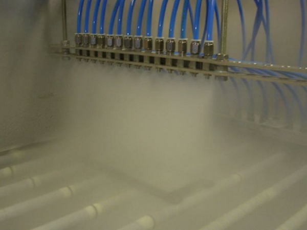
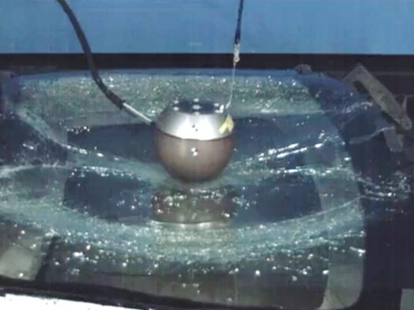
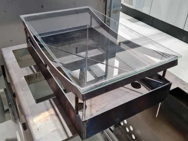
New production technologies allow the efficient production of curved glass and make glass an ideal material for panelized freeform surfaces (see Figure 2). Geometrically, glass can cover the full spectrum of flat, single curved, and even double curved panels with almost arbitrary boundary curves. Double curved molded panels, however, are still significantly more expensive to produce than machine-formed cylindrical panels.
Flat glass panels are still by far the cheapest. Fortunately, new insights on the cold bending behavior (e.g., [11]) of glass demonstrate that glass allows enough bending flexibility to allow for geometric cost optimization by maximizing the use of simple shapes and the repetition of more complex shapes (see Section 2.3 for a more detailed explanation of this connection).
.jpg)
Figure 2 Two recent projects with curved glass. Top: Lentille of Saint Lazare Metro Station, Paris, A.R.T.E. J.M Charpentier & Associés, RFR. Bottom: Strasbourg Train Station, NCF DAAB Agence des gares, RFR. These surfaces are not freeform surfaces in the strict sense since they are both modeled from basic geometric primitives like tori and spheres.
This paper studies the implications of state of the art research in architectural geometry to paneling architectural freeform surfaces with glass panels. Evolute is a geometry consulting company that has substantially contributed to the advancement of architectural geometry and has implemented a general framework that makes all the recent results from research available to the industry. In this paper we apply our framework to the scenario of paneling an architectural freeform surface using flat, single curved, and double curved glass.
The Eiffel Tower Pavilions designed by the architects Moatti et Rivière will replace the old Pavilions on the first platform of the Eiffel Tower (www.eiffel-tower.com) as part of a redevelopment of the first platform that will be performed in 2012 and 2013. Evolute has collaborated with the engineers RFR to provide a structurally and geometrically elegant and efficient solution for the pavilion’s front façades, that expresses our admiration for the elegance, prestige, and tradition of the hosting building.
Besides our work on the paneling of the freeform façades, which is described in this paper, we also optimized the geometry of the freeform structure supporting the glass panels, such that it can be efficiently realized with single curved steel beams. We will publish results and insights from this work in the near future. Interested readers are invited to visit www.evolute.at for an overview of Evolute’s work and publications.
In this paper we present several case studies for paneling the Eiffel Tower Pavilions, including the solution that was eventually chosen for the project. In these case studies we explore and evaluate the possibilities that Evolute’s new computational tools present to glass as an architectural material. We shortly review the underlying research results and provide insights to some specific practical challenges and solutions not discussed in classical research publications. The case studies illustrate how advanced geometric tools enable the cost-efficient realization of complex architectural designs with glass.
2 Freeform paneling with glass
At the beginning of an architectural freeform project the architect usually designs the freeform surface as a smooth NURBS surface or a surface mesh. Since this surface is the design reference for any later step we call this surface the reference surface. Figure 3 shows the reference surface for the front façade of one of the Eiffel Tower Pavilions. To realize the design, the surface is to be decomposed into glass panels of manageable size, in this case around 70 panels.
Obviously, this is not a large-scale panelized surface. The medium scale and the still relatively high curvature variation of the reference surface, however, make the project an ideal case study for illustrating the important aspects of paneling. All the techniques and results discussed below also apply to large-scale projects with thousands of panels (see [9,10] for further examples).

Figure 3 The freeform reference surface (left) and the curve network (right) used for our case studies.
The pattern produced by the panel boundaries typically defines a collection of curves that we call the curve network. Since the curve network is usually visible in the final building (see, e.g., Figure 2) it is an important visual element and is thus often designed by the architect together with the reference surface. The layout of a visually pleasing curve network can be a challenging task itself and can for example be solved by using commercially available software such as EvoluteTools for Rhino (www.evolutetools.com). In this paper, we assume that the curve network is given as part of the reference design (see Figure 3).
The curve network defines how the panel boundaries will be cut. For some applications, cutting curves that lie in a plane might be desired. Our optimization framework can incorporate additional requirements on the curve network and can handle planar curves as well as general space curves. To illustrate this, we used a curve network with straight curve segments for the case studies with planar panels (Section 2.1) and planar curve segments for the case studies with double curved panels (Section 2.3).
The paneling problem is to approximate the reference surface and reproduce the curve network with a collection of panels. As we will see, the most powerful solutions minimize the cost of the panelized surface while achieving the desired quality.
The quality of a panelized surface is mainly determined by the gaps (“divergences”) and the angles (“kink angles”) between neighboring panels (Figure 4). Depending on the panel shapes, panels might not smoothly align, which will strongly influence the visual quality of the surface and the reflections on the surface. Using more complex panel shapes results in a smoother panelized surface. This usually stands in direct conflict to the objective to minimize cost.

Figure 4 Divergences and kink angles between neighboring panels are crucial quality measures of a panelized freeform surface.
Cost is often directly related to the geometric complexity of the panels. Minimizing cost means preferring simple panel shapes like planes or cylinders as well as exploiting the repetition of the same panel shapes at different parts of the surface. The cost of glass panels is directly linked to the type of curvature. Therefore, we organize the case studies into the categories planar, single curved, and double curved panels. We show how our general framework ensures high quality results for various panel types and budgets.
2.1 Planar panels
The most cost-efficient way to realize a freeform surface with glass is to use planar panels. For triangulated curve networks, paneling with planar glass is trivial, since the three corner points of a triangle always lie in a plane. For 4 corner points (quadrilateral pattern as in Figure 3) or more, the curve network does not automatically define a planar paneling. Figure 5 shows the solution for our reference surface and curve network shown in Figure 3. Our framework will optimally align the planar panels to reduce divergences and kink angles between the neighboring panels.
As we can see in Figure 5, however, as soon as the reference surface is curved, the kink angles will be high and the surface will have a faceted appearance mainly visible in the discontinuous reflection and refraction pattern on the surface. Another disadvantage of planar quadrilateral panels is that there are rather strict conditions on the curve network layout to ensure low divergences. Ideally, the curve network follows a so-called conjugate curve network on the reference surface [4].
Given a good curve network, however, our framework can produce very low divergences (order of millimeters) even for highly curved surfaces. As described at the beginning of Section 2, a curve network with straight panel cutting curves was used for this result, which enables easy and efficient cutting of the panels. Even though the panels are planar, however, straight panel cutting curves are not a requirement of our framework and non-straight cutting curves, as the ones shown in Figure 3, could be used as well.

Figure 5 Paneling solution with planar panels. Leads to a faceted appearance mainly visible in the discontinuous reflection and refraction pattern on the surface.
2.2 Single curved panels
A nicer surface reflection and refraction pattern, i.e., lower kink angles, can be achieved with single curved panels. The divergences achievable with single curved panels are also depending on the geometric properties of the curve network [6] but there is more flexibility for the curve network layout due to the higher flexibility of the panel shapes.
Single curved panels can be smoothly aligned along strips (Figure 6) producing to a nice “semi discrete” pattern. This is a good solution if general developable glass panels can be manufactured. Unfortunately, general single curved glass is still very expensive to produce.

Figure 6 Paneling solution with single curved panels. Produces a regular pattern of smooth strips but can be very costly to realize with glass.
A much more relevant glass paneling in practice is a paneling with cylinder panels, because cylindrical glass can be produced cost-efficiently through hot or cold bending, allowing for thermal tempering. Due to the high practical relevance, we investigate several possibilities for cylinder paneling in more detail:
Cylinder Paneling 1 – Local fitting
Figure 7 shows the industry standard solution of cylinder paneling before research in Architectural Geometry: the best fitting cylinder is computed for every surface segment defined by reference surface and curve network. Since this method aligns every cylinder separately, the neighboring cylinders do not fit together very well, which leads to high divergences (Figure 7).

Figure 7 Paneling solution with local cylinder fitting. Leads to large divergences of over 2 cm as demonstrated on a single strip.
Cylinder Paneling 2 – Global fitting
Instead of aligning each cylinder separately, divergences can be drastically reduced by computing an optimal alignment for all cylinders simultaneously [9,10]. Figure 8 shows the result of such a global fitting optimization with very low divergences. To produce a maximally smooth surface, however, the optimization framework aligns the cylinders in an irregular way, which might be undesirable by the architect.

Figure 8 Paneling solution with global cylinder fitting. Achieves low divergences but results in an undesirable change of cylinder alignments as can be seen in the opaque rendering (bottom). Max divergence: 17 mm. Max kink angle: 3.7 degrees.
Cylinder Paneling 3 – Global fitting with kink angle control
To obtain a more regular cylinder alignment pattern, we extended our framework with the possibility to interactively design the directions in which the kink angles should be low or not (see [10] for further details). This enables the user to explicitly align the cylinders along prescribed directions. For our case study, we simply specified that the kink angles should only be low along the strips in the vertical direction.
Since not all the kink angles have to be optimized anymore, the optimization has more freedom and generates a cylinder strip paneling with low kink angles along the strips and extremely low divergences everywhere (see Figure 9). A small deficiency of the solution, however, was immediately noticed by the trained eye of the architect: the opaque rendering in Figure 9, bottom, clearly shows, that the transitions from one strip to another are not very regular; the angles are rather large between some strips and small between others.

Figure 9 Paneling solution with global fitting and kink angle control. The cylinders are now nicely aligned along strips as clearly visible in the opaque renderings. A close inspection shows slightly irregular angles from one strip to the next. Max divergence: 3.4 mm. Max kink angle along strips: 0.9 degrees. Between strips: 6.2 degrees.
Cylinder Paneling 4 – Global fitting with advanced kink angle control
To resolve the irregular kink angles between the vertical strips (Figure 9) we extended the framework by adding an optimization that tries to make the angles between the strips as even as possible. The opaque renderings in Figure 10 show that this extension leads to a clearly improved regular distribution of the strips compared to the one in Figure 9, while achieving low divergences smaller than 3.6 mm. This example demonstrates that in practice specialized solutions, tailored to the specific project, are often required and thus every project still offers new and exiting challenges to the geometry consultant.
This solution was eventually chosen as the basis for the solutions of the Tour Eiffel Pavilions’ front façades. Further specialized optimizations where performed and practical requirements on the paneling and the substructure had to be considered for the final geometry. We were able to keep the low maximal kink angles along the strips of around 0.4 degrees and achieved even lower maximal divergences below 1.5 mm with a maximal deviation from the original reference surface of around 12 cm.

Figure 10 Global cylinder fitting with advanced kink angle control leads to a very smooth cylinder strips paneling. Max divergence: 3.6 mm. Max kink angle along strips: 0.4 degrees. Between strips: 6 degrees. This result served as the basis for the Tour Eiffel Pavilions and the final Pavilion Paneling achieved max king angles of around 0.4 degrees along strips with max divergences below 1.5 mm!
2.3 Double curved panels
The highest surface quality can be achieved using double curved panels. Creating a custom shape for each panel can produce a perfectly smooth solution. This perfect solution, however, is usually also the most expensive one. Between the solution with only custom panels and the solution with only planar panels lies a whole range of solutions defining a tradeoff between approximation quality and cost. In [9,10] we argue that the best way to resolve this tradeoff is to give the user control on this tradeoff by letting him specify desired quality constraints.
In practice, two measures of quality have proven to be the most relevant: divergences and kink angles (see beginning of Section 2 for definitions). Our framework thus tries to solve the paneling problem with minimal cost while meeting user specified constraints on the divergences and kink angles between neighboring panels. By guaranteeing that the constraints on divergences are met, the framework automatically reduces the risk induced by cold bending the panels to close the gaps.
In practice, two important cost factors are the panel types and the mold reuse. Geometrically simpler panels are usually cheaper than more complex ones. In our framework we implemented the following 5 panel types (see Figure 11): plane and cylinder, because they are the most relevant for many materials including glass; parabolic and torus patches, because they carry families of congruent profiles which can reduce cost in the production process; and cubic patches, because they have a high geometric flexibility and can approximate even complex shapes with high accuracy.
The optimization framework is very flexible and further panel types have already been added in the meanwhile, like cones, general cylinders, and ruled surfaces. Usually, planar panels are the cheapest to produce, followed by cylindrical panels and then the more costly double curved panel types. Curved panels are often produced by a molding process, i.e., first a mold is created and then this mold is used to produce the panel. Since the cost of creating a mold is usually much higher than the cost of creating a panel using this mold, significant cost savings can be achieved when the same mold is reused to create several panels. For these reasons our optimization framework tries to prefer simple panels and maximize mold reuse.

Figure 11 The panel types used for the results in Figures 12 and 13.
As already mentioned in the introduction, there is thus a strong link between divergences and kink angles and the cost of a paneling solution. The larger the allowed divergences and kink angles, the more cost can be saved by using only simple panels and reusing the same mould many times. Figures 12 and 13 demonstrate this relation between quality and cost. In both solutions the divergences were constrained to lie below 6 mm. The solution of Figure 12 was computed by setting a kink angle constraint of 1 degree. The solution of Figure 13 was computed using a kink angle constraint of 0.25 degrees, leading to a smoother but also more expensive solution.
The impact of the kink angle constraints on the paneling quality is mainly visible in the smoothness of the reflection and refraction pattern on the panelized surface. Through these constraints, our framework offers direct control on the cost-quality tradeoff and is able to significantly reduce production costs by more than 70% of the costs of the current industry standard achieving the same quality [9]. As described in the beginning of Section 2, to illustrate the flexibility of our framework, a curve network with planar cutting curves for the panels was used for the results in this Section.
Because of the non-smooth curve network, the resulting paneling might look less smooth then expected. The smootness of the panelized surface, however, should not be confused with the smoothness of the cutting curves. A panelized surface can be perfectly smooth, which is mainly visible in the perfectly smooth reflection and refraction pattern, but can still have a non-smooth curve network with sharp corners and straight elements. The same results as in Figures 12 and 13 could have been produced with a smooth curve network like the one used for single curved panels in Section 2.2.

Figure 12 Paneling with double curved panels by prescribing divergences lower than 6 mm and kink angles lower than 1 degree.

Figure 13 Paneling with double curved panels by prescribing divergences lower than 6 mm and kink angles lower than 0.25 degrees leads to a smoother but also more expensive solution. The improved smoothness is mainly visible in the reflection and refraction pattern on the panelized surface.
3 Conclusion and future work
In this paper we reviewed the recent findings from the field of architectural geometry in the context of paneling architectural freeform surfaces with glass panels. We demonstrated on several case studies for the Tour Eiffel Pavilions how the computational framework and the state of the art geometric expertise allows Evolute to find excellent paneling solutions for any demand on budget and quality. The paneling solutions can be tailored to the specific needs of the project and support all current shape families of glass panels (planar, cold- or hot-bent).
A central challenge for future work is to make the paneling of freeform surfaces an interactive process. For large-scale projects, computing a paneling with double curved panels can take hours. Therefore, the paneling optimization is usually still decoupled from design and it is not possible to obtain direct feedback about the paneling during designing a freeform surface. The recently introduced EvoluteTools for Rhino www.evolutetools.com is a step towards more interaction, at least for paneling with planar and single curved panels. In the context of glass, the specific geometric possibilities of cold bending, e.g., large cold bending deformations of previously hot bent glass, will be further investigated.
References
[1] H. Pottmann, A. Asperl, M. Hofer, and A. Kilian: Architectural Geometry. Bentley Institute Press, 2007.
[2] H. Pottmann, M. Hofer, and A. Kilian (editors) (2008): Advances in Architectural Geometry, Conference Proceedings. Vienna University of Technology, 2008.
[3] C. Ceccato, L. Hesselgren, M. Pauly, H. Pottmann, and J. Wallner (editors): Advances in Architectural Geometry, Conference Proceedings. Springer, 2010.
[4] Y. Liu, H. Pottmann, J. Wallner, Y.-L. Yang, and W. Wang: Geometric modeling with conical meshes and developable surfaces. SIGGRAPH 2006.
[5] H. Pottmann, Y. Liu, J. Wallner, A. Bobenko, and W. Wang: Geometry of multi-layer freeform structures for architecture. SIGGRAPH 2007.
[6] H. Pottmann, A. Schiftner, P. Bo, H. Schmiedhofer, W. Wang, N. Baldassini, and J. Wallner: Freeform surfaces from single curved panels. SIGGRAPH 2008.
[7] A. Schiftner, M. Höbinger, J. Wallner, and H. Pottmann: Packing circles and spheres on surfaces. SIGGRAPH Asia 2009.
[8] H. Pottmann, Q. Huang, B. Deng, A. Schiftner, M. Kilian, L. Guibas, and J. Wallner: Geodesic Patterns. SIGGRAPH 2010.
[9] M. Eigensatz, M. Kilian, A. Schiftner, N. Mitra, H. Pottmann, and M. Pauly: Paneling Architectural Freeform Surfaces. SIGGRAPH 2010.
[10] M. Eigensatz, M. Deuss, A. Schiftner, M. Kilian, N. J. Mitra, H. Pottmann, and M. Pauly: Case Studies in Cost-Optimized Paneling of Architectural Freeform Surfaces. Advances in Architectural Geometry, 2010.
[11] R. Royer de Vericourt and S. Flöry, Application of inextensional theory to stress calculations in cold-bent surfaces, Glass Processing Days Finland, 2011.
Acknowledgements
The authors wish to thank RFR (www.rfr.fr). This work was supported by the European Community’s 7th Framework “People” Programme through an IAPP project under grant agreement 230520 (ARC).
AUTHORS: Michael Eigensatz, Alexander Schiftner - Evolute GmbH