Authors:
Anthony Barnes, PE - Senior Structural Design Engineer, SC Railing Company
Ted Kraemer, PE - Project Manager, Larson Engineering, Inc.
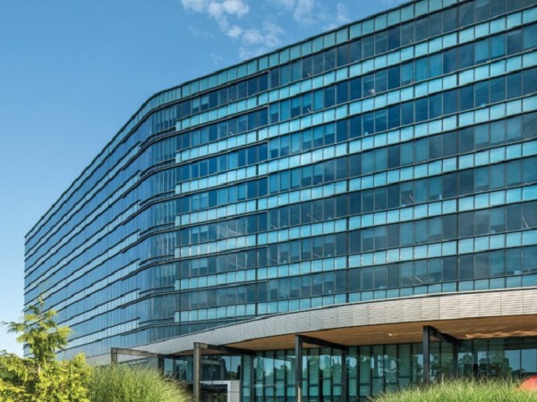
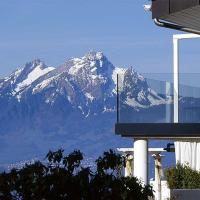
Point supported glass guardrail systems have increased in popularity in recent years becoming more common in commercial building construction. The system offers a modern aesthetic and is architecturally versatile, making the system desirable for architects and owners alike in a wide variety of applications.
Continual advancements over the years both in design and manufacturing technology have allowed for an ever-expanding range of uses, and have made critical the need for consistent engineering practices. This article will provide a brief explanation of typical design requirements and a brief summary of typical designs of point supported glass guardrails.
Design consistency is, as with other engineered building systems, determined by the way building and design codes are used, and the analysis methods selected by designers. Design codes pose an initial hurdle as they are fragmented and seemingly contain redundant and contradictory requirements for glass guards.
At the same time, consistent engineering analysis has been generally lacking. There are several possible reasons for this including the treatment of guards as a product rather than an engineered structure, lack of experience with glass as an engineered material, and a lack of glass design software readily available in the United States.
Design begins with determining the performance requirements set forth by building codes. Methods for calculating allowable glass stress are normally dictated by ASTM E-1300 which provides stresses based on probabilities of glass breakage and duration of load. This standard is referenced by IBC, but is not used specifically to derive the allowable stress for glass guardrails.
The allowable stress for guardrails is specified in IBC section 2407 which states that a factor of safety of four must be used for stresses caused by live loads. Generally, for fully tempered glass, this results in an allowable stress of 6000 psi.
For comparison, the allowable stress on vertical glass as calculated per ASTM E1300 for live loads is approximately 8600 psi. The loads to be applied to guardrails are specified in section 1607 of IBC as a 200 pound concentrated load or a 50 pound/ft. load applied at the location that causes the maximum stress effect.
Building codes do not specify overall deflection limits for guardrails, only that differential deflection between glass panels must be limited to the glass thickness. These differential deflections are usually prevented by the use of top caps or handrails, which are required for all applications except where laminated glass has been approved for use by the jurisdictional authority.
The 2015 IBC further limits the use of monolithic glass by restricting its use in areas above walking surfaces where falling glass could pose safety concerns. In summary, the IBC allowable stress of 6000 psi should be used for glass in guardrails subjected to live loads and ASTM E1300 should only be applied to check glass stresses caused by wind or seismic events.
Glass analysis is the most critical aspect of point supported glass design. Unlike building codes, which offer a limited number of interpretations and uses, there are many different analysis methods and programs that may be employed by engineers.
Regardless of the methods selected, several key principles must always be considered: the elastic properties of laminate interlayers (and how they change with temperature and load duration), understanding that glass is a brittle material and that local stresses are critical, and as such, details at the glass support such as contact material, support size and hole size are important.
In light of these key principles, it’s highly recommended that a good finite element program be used to accurately determine glass stresses instead of any manual analysis. While many such programs exist, not all are catered to panels or glass.
Analysis in this article is developed using SJ Mepla, a program developed in Germany specifically for glass structures. It is used widely amongst design-build glass specialty contractors and engineering consultants working with glass.
With engineering efficiency in mind, we next seek to determine what minimum thickness of glass should be specified for typical point supported guardrail systems. Typical point supported glass guards consist of point supports at the bottom of the glass.
The number of supports and the dimensions can vary. Figure 1 shows a typical panel with 6 nodes. Typical panel height is usually 54” (guards are required to be 42” in height) as panels are often mounted to the sides of stairs and overlooks. Fittings vary, but typically for guards consist of 2”-3” discs resting on the glass surfaces and supported by the building structure. Top cap and/or handrail can be used to connect panels.
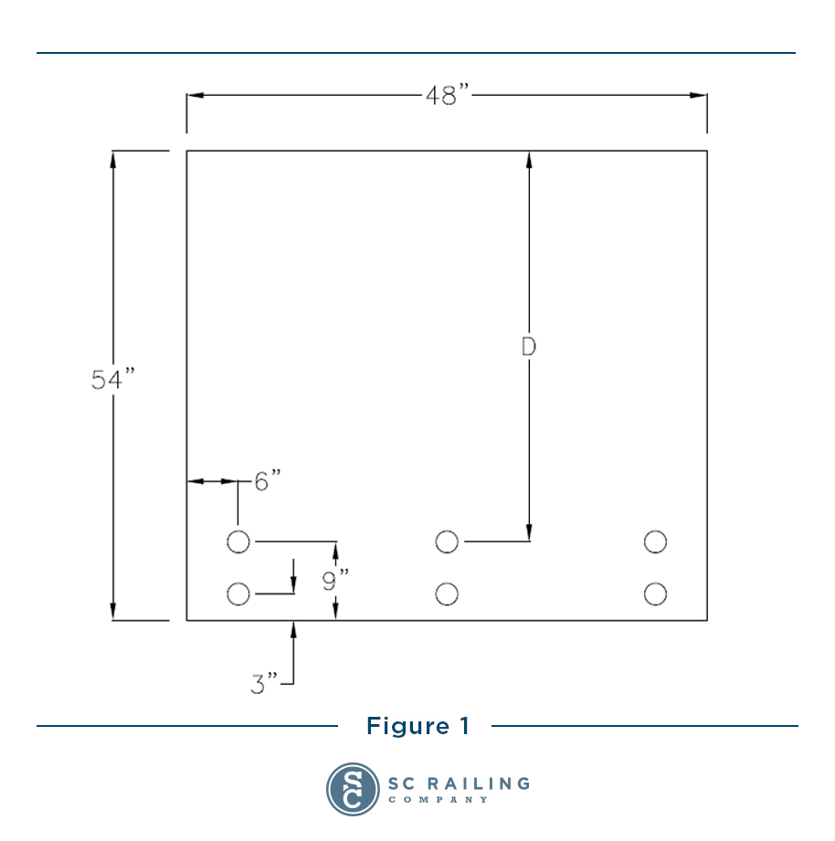
Analyses were performed indicating trends while looking at two primary factors that affect glass stress: distance from top of glass to uppermost point support, D in Figure 1, and thickness of glass. The glass support fitting is not allowed to rotate, and rigid plastic nylon spacers are used between the fitting and the glass.
The 50 pounds per linear foot is applied across the entire length of the top of the glass. This is considered to cause the highest glass stress, assuming that handrail or top cap could be present which would effectively transfer the 200 lb. concentrated load to adjacent panels. Note that the top cap or handrail does not add strength when the distributed load of 50 lbs./ft. is applied because it is assumed that all panels are loaded simultaneously. Thus, rail or cap attached to the guard is simply moving with all panels as they deflect.
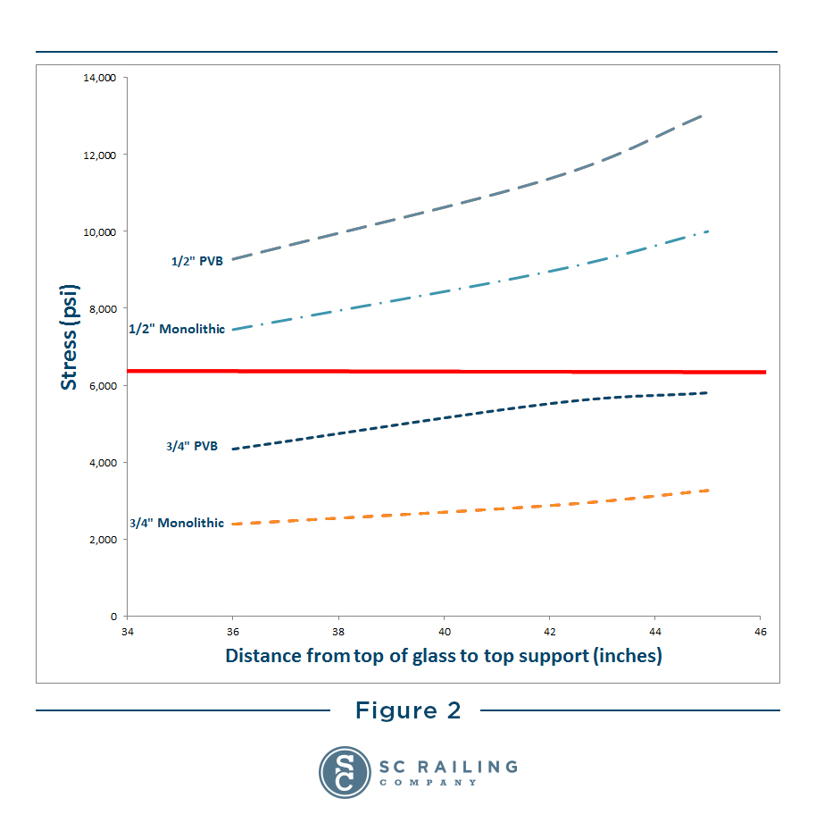
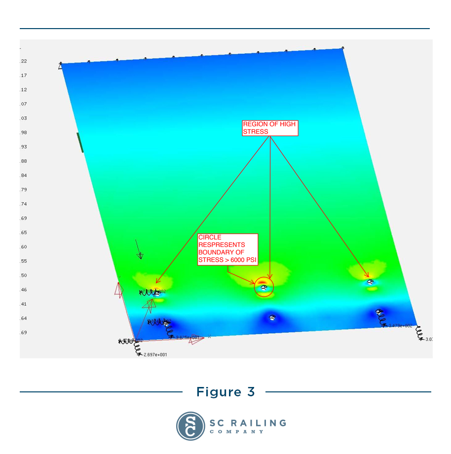
Figure 2 indicates that ¾” glass, either laminated or monolithic, meets the IBC performance criteria while ½” glass of any type does not. While moving the nodes towards the top of the glass decreases stress, moving them up so that the distance is below 36” is usually not practical or is architecturally undesirable. Note that stress in better performing interlayers will lie somewhere between the monolithic and PVB curves. Figure 3 is a stress plot and shows that stress for ½” glass is above the allowable value at the top fittings and in an area slightly larger than the fitting diameter.
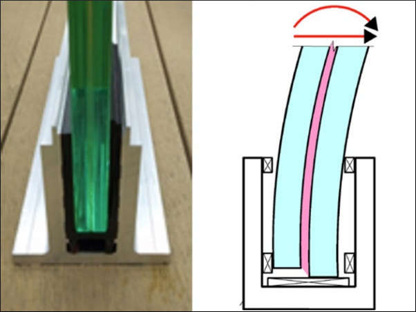
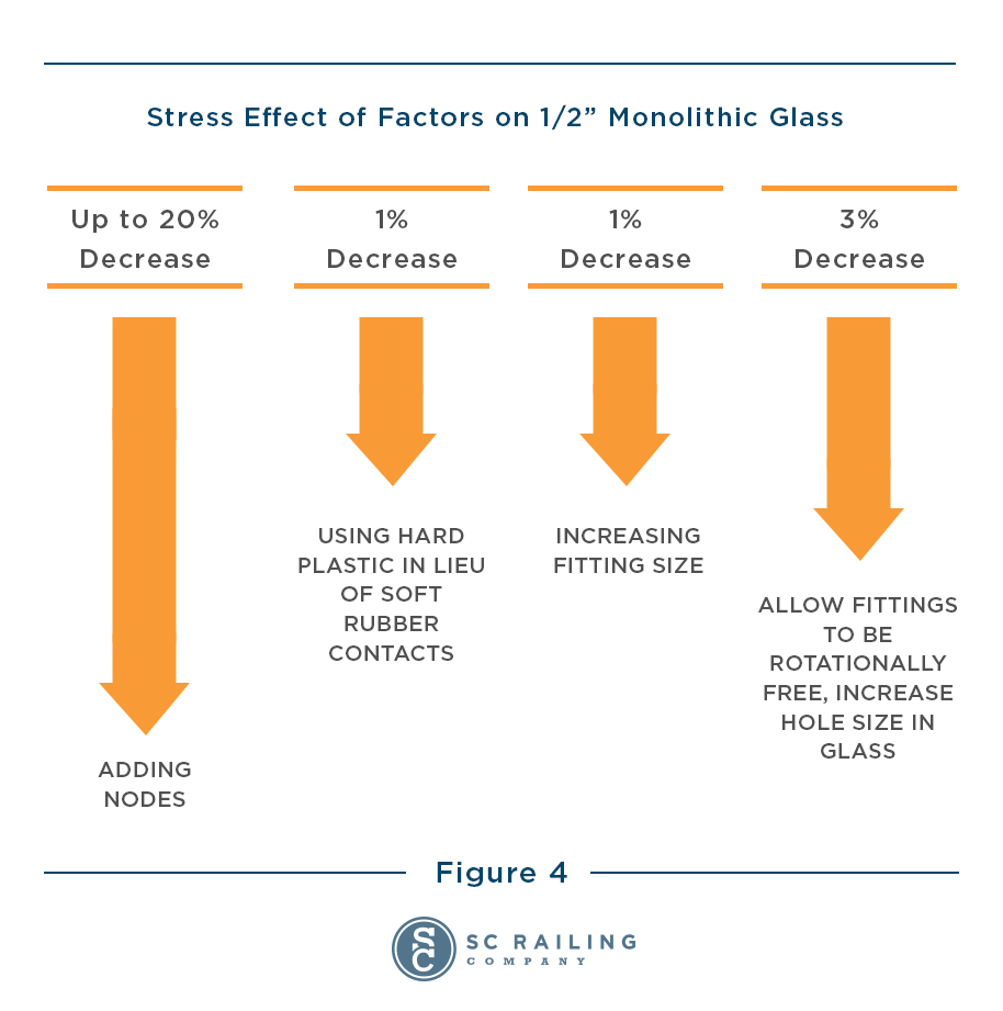
The stress distribution can be altered by modifying one or more of the following: the number and size of fittings, the fixity of the fittings, contact material. Generally speaking, these modifications have effects as shown in Figure 4. These trends are not constant for all glass types and configurations (for example, stress can be reduced by increasing fitting size and using soft rubber) but represent generally good rules of thumb.
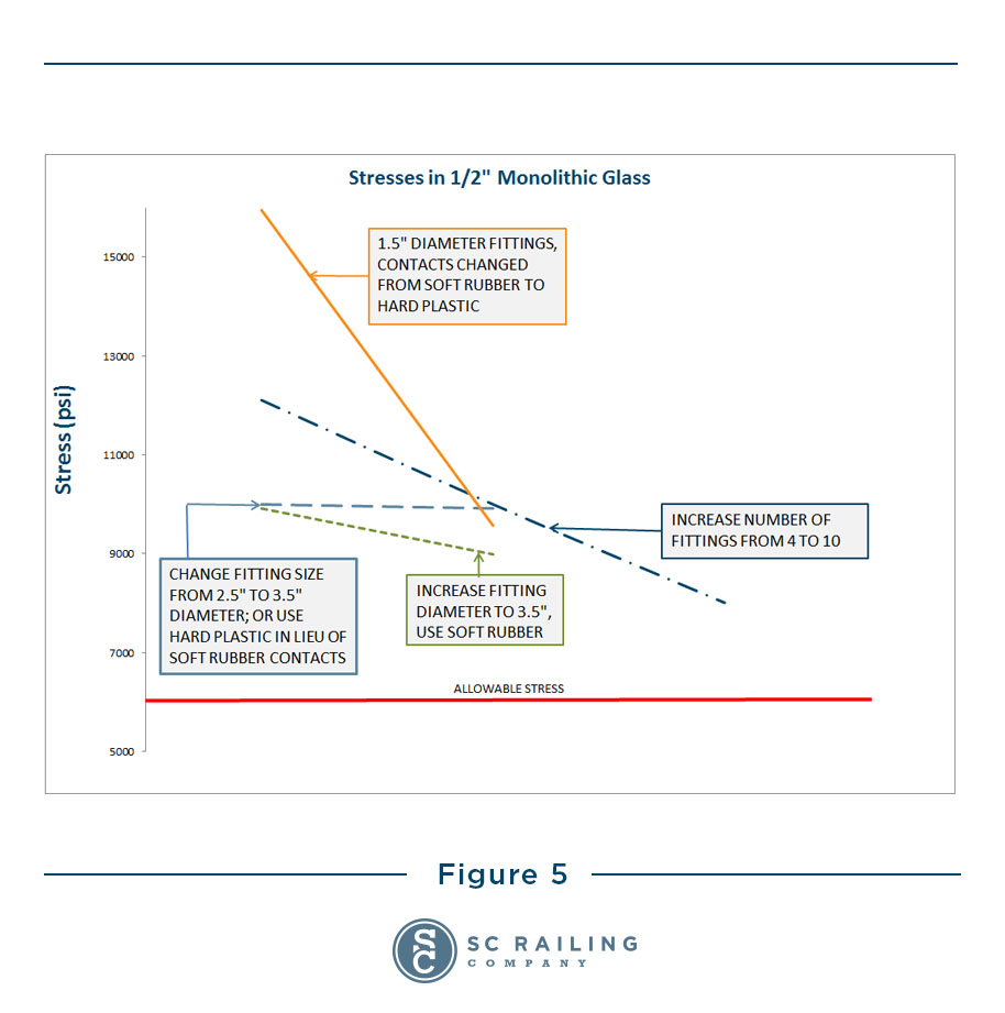
Adding nodes has the most significant impact on lowering stress, but is likely the most costly as well. Figure 5 shows stress values in ½” monolithic glass resulting from modifying these variables. The distance from the top of the glass to the top fitting is held at 45”. Various changes to the fittings are made, but in all cases, the stress is never less than around 8000 psi, which is greater than the 6000 psi limit.
Beyond the aesthetic charm of the system is the practical application of life safety. It’s essential that those who have a stake in a project understand this and take appropriate measures to ensure that building code requirements are met. Analyses of some typical configurations indicates that ¾” glass, either monolithic or laminated, meets IBC stress requirements, while ½” glass of any type does not. Modifying the number of fittings, fixity of supports, contact materials, position of supports and increasing the number of fittings decreases glass stress, but in any case does not allow for glass thickness reduction below ¾”.
Analysis data and additional information is available upon request.