The Paper "Laser-Grown Bumps on Window Glass" was first presented at GPD 2017 by Alexander Streltsov, Jin Kim, Leonard Masters, and David Lance from Corning Research & Development Corporation Corning, New York, USA.
Abstract
The process of forming bumps on window glass with an ultra-violet nanosecond laser is described. Bump growth is caused by heating the glass to temperatures above the softening point. Directional flow carries the softened glass towards the surface forming a bump. The shape of the bump is mostly determined by the surface tension of the molten glass.
We show that the height of the bumps, which are typically approximately 180 µm tall, can be controlled with sub-micrometer accuracy and the shape can be altered from semispherical to flat-top. The time required for growing a bump is on the order of a second or less. These bumps may be an alternative to the metal posts in the incumbent vacuuminsulated glazing designs.
Introduction
Vacuum Insulated Glazing (VIG) concept allows for a significant improvement of thermal insulation compared with the incumbent double-pane windows design.
Existing VIG designs incorporate pillars of stainless steel as spacers to prevent the glass panes from touching each other under atmospheric pressure. Some of the issues of metal pillars are 1) high thermal conductivity compared to other materials (e.g. ceramics, glass), 2) parts/material cost, and 3) manufacturing yield or throughput.
For a VIG unit with window size of 1 m2 and array spacing of 20 mm, about 2,000 pillars are required to be placed on a pane, adding significant cost to the VIG unit. Lastly, after metal pillars are placed on a pane, moving the pane carefully through the manufacturing process without disrupting the position of pillars compromises manufacturing yield and/or throughput.
Thermal conductivity: The spacers grown from glass pane have thermal conductivity significantly lower than that of metal. It is known that heat conduction through spacers is the major factor that determines overall insulation of a VIG unit [1]. So, changing the spacer material from metal to glass will significantly improve thermal insulation of a VIG unit.
VIG manufacturing cost can be significantly lowered with laser-grown bumps. Lower manufacturing cost is enabled by lower material cost, higher production yield, and higher throughput.
Material cost: VIG with laser-grown bumps does not use discrete materials for spacers, whereas VIG with metal pillars does use discrete materials, i.e., metal pillars, which increases material cost. For VIG with lasergrown bumps, glass spacers are grown out of the pane. For VIG with metal pillars, metal pillars are formed first by masking and etching a metal sheet and then introducing the pillars on the pane.
Manufacturing yield or throughput: For VIG with laser-grown bumps, the glass spacers are attached to (or a part of) the pane. This permanent bond prevents any movement throughout the production steps. In contrast, when metal pillars are placed on the pane, especially with anti-friction coating on them, careful handling is required in order to prevent pillars’ movement, sacrificing manufacturing yield and/or throughput.
We propose to use laser-grown glass bumps as spacers for VIGs. Laser-grown glass bumps can solve many of the problems associated with metal pillars. The advantages come in terms of thermal conductivity, material cost, manufacturing yield, and throughput.
In the following sections, we will describe how glass bumps are made in various forms with high accuracy for the application to vacuuminsulated glazing.
Bump Growth Process
The mechanism of creating bumps on transparent glasses is described in [2,3]. The output of a 355nm, nanosecond laser is directed through the soda-lime (window) glass substrate such that the focus is behind the rear surface (Fig. 1a). The substrate is kept at room temperature.
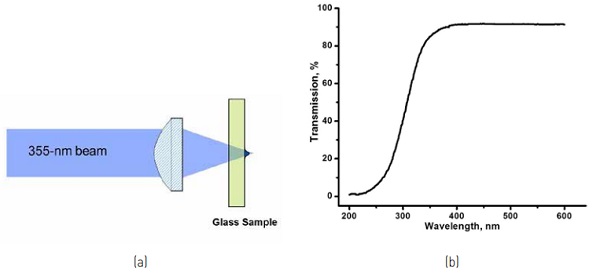
Although the soda-lime glass is quite transparent at 355 nm (Fig. 1b), its absorption effectively increases when exposed with highintensity laser radiation due to multi-photon absorption. This is why focused laser beam causes heating of the glass through increased absorption. Heating results in glass melting and its directional flow/expansion towards the rear surface of the glass thus forming a swelling. The shape of this swelling is defined by the surface tension of molten glass. When the laser is switched off, the swelling freezes first due to radiative cooling followed by quenching of the molten volume inside the glass.
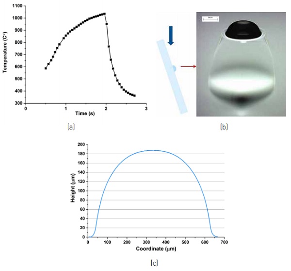
Fig. 2a shows the temperature of the glass surface where the bump is grown measured with a thermal camera. The glass is irradiated for approximately 2 s with a 15 W, 355 nm, nanosecond laser (Coherent AVIA-355-20) to the temperature above the working point of 1000 °C (corresponding to the104 P viscosity). After the laser is switched off, the bump cools down to below the strain point (~ 400 °C) in less than 1 s.
Fig. 2b presents the microscope photo of the laser-grown bump on 4-mm thick soda-lime (window) glass. This side view shows the semi-spherical profile of the bump, which is about 190 µm tall and 500 µm in diameter. The characteristic ratio between the diameter and the height lies usually in the 2.5-3 range. The volume below the bump, which is visible because of the lower refractive index, is under tension. This tensile stress goes away when the glass article with bump(s) is brought above the annealing point. The bump profile is shown in Fig. 2c.
The maximum bump height depends on a number of factors: glass composition, thickness, and laser conditions. Thicker glass allows for taller bumps because of larger molten and expanding volume. Glass composition defines the visco-elastic, thermal, and optical properties of the glass. The role of viscosity is not fully understood at this moment; however, it is obviously easier to make bumps on low-temperature glasses compared with the refractory ones.
Optical properties, specifically linear and nonlinear (laser intensity dependent) absorption, determine the requirements for the laser conditions. Higher laser power results in taller bumps unless excessive laser power causes glass ablation rather than swelling. Similar limitations are applied to exposure duration: long exposure may cause ablation or re-melting of the bump and its reflow resulting in height decrease and in diameter increase. In general, increasing the laser power allows for shorter irradiation times for the same bump height.
For a 4-mm thick window glass and 180 – 190 µm bumps, the lower limit for the irradiation time is around 0.75 – 1 s because of time required for heating the glass beyond the working point and giving time for it to flow. Shorter bumps require less time, although their height should not be less than approximately 150 µm. The minimµm bump height is limited by the thermal conductance of the residual gas in the VIG and by evanescent coupling.
Bumps like these can be fabricated on a range of transparent glasses. Besides a regular soda-lime (window) glass bumps can be grown on Ultra-White window glass, which has lower iron content and does not have the typical greenish tint of the regular window glass. The heights of the bumps are basically the same as on the regular window glass.
Bump Height Control
The glass pillars must have the same height in order to maintain uniform contact with the flat glass surface of the second glass pane. If the bump height variation is approximately greater than +/- 1µm the stresses on the taller bumps will be significantly higher than on the shorter bumps. This uneven stress distribution caused by excessive bump height variation within the VIG unit will likely result in reduced thermo-mechanical performance and in lower mechanical strength overall.
We achieve improvement in height variance by using a feedback signal to control the duration of glass irradiation with a laser when growing a bump. The bump gets taller with longer laser irradiation duration and by adjusting this duration one can control the bump height.
However, depending on the variation of glass properties and the fluctuations of laser power, the bump size may vary even for fixed irradiation durations when the fixed interval is based on the opening and closing of a laser shutter. To overcome these perturbations, a controlling feedback signal is used, which is based on the bright flash of light coming from the rear side of the glass, where the bump is grown. The bright flash is registered by a photodiode.
This flash takes place a fraction of a second after the laser exposure starts. It is this bright flash that marks the beginning of the fixed duration rather than the opening of the shutter. The glass is irradiated for a fixed duration of time after this flash thus controlling the exposure time in the regime where the bump is growing [4]. Controlling laser irradiation in this manner allows for a noticeable reduction in the variance of bump height.
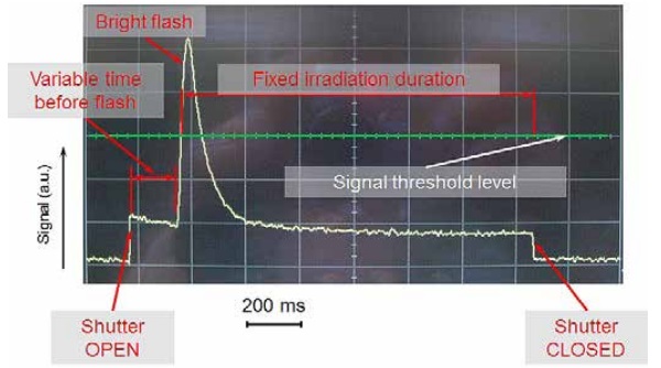
In Fig. 3, an example of the feedback signal from a photodiode (as viewed on an oscilloscope) is shown. The profile shows a jump in signal when the laser shutter is first opened up. The time between shutter open and bump growth initiation is variable and may depend on glass material property variation as well as laser power variation among other factors. Once bump growth begins, a much stronger spike is registered and it is this signal that is used as a start time for the fixed irradiation interval. A threshold level is chosen that is ~50% of the typical height of the bump growth signal. Once that threshold is overtaken, then the timer begins. The fixed irradiation time is chosen according to the desired bump height.
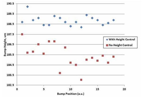
Fig. 4 shows the results of growing two populations of bumps. One population is generated using the height control method and the second is generated without height control. It is readily apparent that the variation in the bump height is noticeably reduced. The average height is also different between the two populations but that is ancillary to the experiment. Laser parameters could have been tweaked such that the average of the bump heights would be approximately equal. It is the variance reduction between the “no height control” population and the “with height control” population that is important. Table 1 below quantifies the statistics between the two populations.
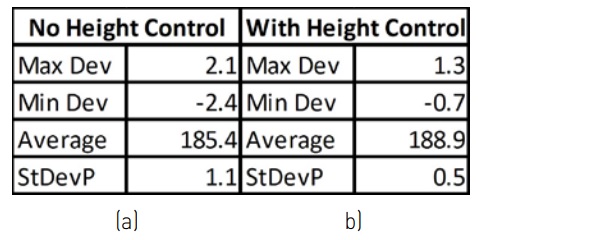
Table 1 shows that the variance or standard deviation of bump height for the “with height control” population is reduced by more than half compared to that of the standard deviation of the “no height control” population. Also, the maximum deviations from the average height are also reduced.
Flat-top bumps
Previous sections described growing quasispherical bumps on glass. These bumps have a limited contact area with a flat pane in the VIG, resulting in significant stresses in the flat pane. Flat-top bumps offer a means to reduce the stresses by increasing the contact area between the bump and the flat pane, resulting in improved mechanical performance. In fact, thermal performance may improve by allowing for larger bump array spacing.
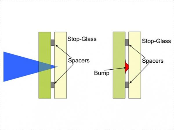
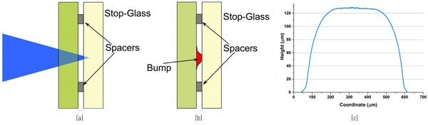
Flat-top bumps were grown by placing a “stop” glass behind the window glass, on which the bump was grown. The glasses were separated by 100-150µm gap defined by the shims placed in between (Fig. 5a). The laser beam was focused behind the windows glass and, in the described configuration; its focus was inside the “stop’ glass.
Fused silica was selected as the material for the “stop” glass substrate because of its high softening point and because molten window (soda-lime) glass will not wet fused silica and will not stick to it.
The intensity of the 15 W focused laser beam was high by itself and the additional focusing provided by the growing bump re-focused the beam onto the surface of the “stop glass”. Even a polished fused silica substrate, having quite high laser damage threshold, developed a crater on the surface from surface ablation making it useless.
The problem was solved by grinding the top surface of the “stop” glass substrate flat and leaving a frosted polish. This prevented the damage of the “stop” glass and allowed for multiple reuses of the same spot for bump flattening (Fig. 5b). The resulting profile of the flat-top bump is shown in Fig. 5c. The bump height is about 130µm, which was determined by the 130µm shims in between of the glasses. The diameter of the contact area between the bump and the flat pane, which can be quantified as, say, the bump diameter at the -3% height, is ~ 260µm compared to ~ 70µm for the semi-spherical bump.
Conclusion
We described the technique of making bumps (pillars) on window glass by laser-induced glass swelling. The bumps may be a costeffective alternative to the incumbent metal pillars as spacers in VIG while their attributes and thermo-mechanical performance are on par or better than that of metal pillars. The bumps have potential to lower the material cost and improve the manufacturing yield associated with metal pillars.
References
[1]. C. Kocer. The thermal and mechanical performance of a vacuum insulated glazing. Glass Performance Days 2015 Conference Proceedings, (2015) 37-40.
[2] S. Logunov , J. Dickinson, R. Grzybowski, D. Harvey, A. Streltsov, Laser-induced swelling of transparent glasses, Applied Surface Science, 257 (2011) 8883–8886.
[3]. US patent 8,616,023 (2013). R. Grzybowski, S. Logunov, A. Streltsov. Raised features on transparent substrates and related methods.
[4]. US patent 9,359,252 (2016). LT Masters and A. Streltsov. Methods for controlled laser-induced growth of glass bumps on glass articles.
[5] US patent 9,346,710 (2016). R. Grzybowski, D. Harvey, A. Streltsov. Sheet glass product fabrication with growth-limited glass bump spacers.